
About this manual
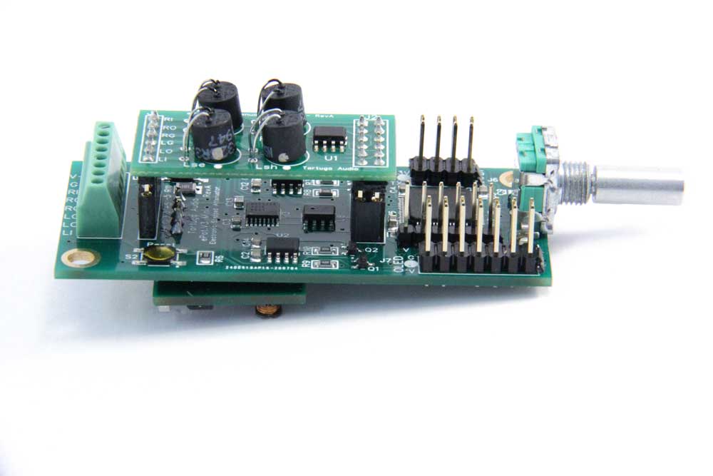
This document primarily describes the physical hardware and installation of the ePot.V3 Mini (the “Mini” ) panel mounted electronic stepped attenuator. The detailed operation and control of the Mini will likely be covered in another manual once it’s ready.
What is the ePot.V3 Mini?
The ePot.V3 Mini (the “Mini” ) is a panel mounted electronic stepped attenuator that offers exceptional sonic performance with advantages that no mechanical attenuator can match.
The “Mini” is literally a direct physical replacement for any volume potentiometer or mechanical stepped attenuator that through-hole mounts directly into a typical front panel, is secured by a nut and washer, to which you then attach a conventional volume control knob.
The ePot.V3 Mini is intended for any DIYer, designer or OEM who is looking for a high performance volume control alternative to conventional potentiometers or mechanical stepped attenuators.
Comparison of the ePot.V3 Max vs. Mini
The Max and Mini are based on the same core hardware design and run essentially the same firmware.
The 3 most significant differences are that: 1) the Mini has no input switching (single input only); 2) and the Mini does not have built-in LDR calibration; and 3) the Max must be chassis mounted while the Mini can be mounted directly into a front panel as would a conventional potentiometer or stepped attenuator.
Here is a comprehensive comparison showing similarities and differences.
| ePot.V3 Max | ePot.V3 Mini | |
|---|---|---|
| Size | 2.7 x 4.4 inch | 1.35 x 2.9 inch (67% smaller) |
| Input Switching | Yes - built-in switching between 6 stereo input channels | No switching - single stereo channel |
| Mounting | Chassis mounted w/ standoffs (not included) | Panel mounted via integral board mounted encoder (like a potentiometer) |
| Balanced Audio | Yes - requires 2 separate boards and a 2 wire serial data link | No - single-ended only |
| LDR Module Calibration | Yes - built-in | No - Uses replaceable plug-in LDR module or you can use a separate ePot.V3 Max to calibrate any LDR module for any Mini |
| Attenuation Type | Plug-in LDR module | Same |
| Controls | * Rotary encoder (externally mounted) * Apple remote control (infrared) | Same except the rotary encoder is mounted directly to the Mini board by default. If you wish you can order a Mini without the encoder installed. This way you can mount the encoder in the front panel and locate the Mini board itself elsewhere. |
| Display | * Status LED * Optional OLED Display (with encoder and IR receiver interface) | Same except OLED and Status LED are mutually exclusive since they both use the same header |
| Auxiliary Control Header | 6 bit signal for controlling external devices | No |
| WiFi Module | Future capability | Same |
| Microcontroller | 100 pin STM32F2 microcontroller | 64 pin STM32F2 microcontroller |
| Firmware Update | Yes - via USB to 2-wire serial UART link | Same |
| Remote Control | Yes - via Apple remote and externally mounted IR receiver | Same |
| Manual Control | Yes - via rotary encoder (externally mounted) | Yes - via integral board mounted rotary encoder |
Key dimensions
- PCB width – 1.35 inches
- PCB length – 2.9 inches (excluding the encoder bushing/shaft)
- PCB mounting hole center – 0.145 inches from board edge
- PCB mounting hole diameter – 0.15 inches
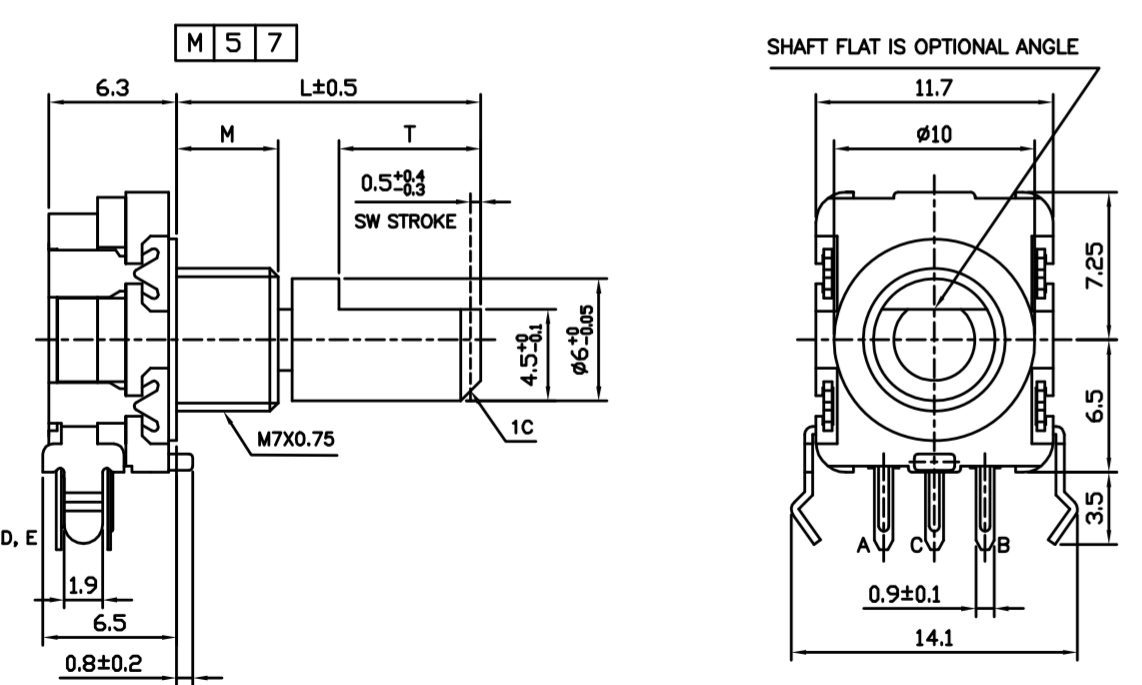
- Encoder length overall beyond edge of PCB (L) ~20 mm
- Encoder bushing length (M) – 5 mm
- Encoder shaft diameter – 6 mm
- Encoder shaft flat length (T) – 7 mm
- Encoder bushing thread – M7 x 0.75
- Vertical clearance/depth – We recommend allocating a 1.5 x 1.5 inch volume of space around the length of the Mini.
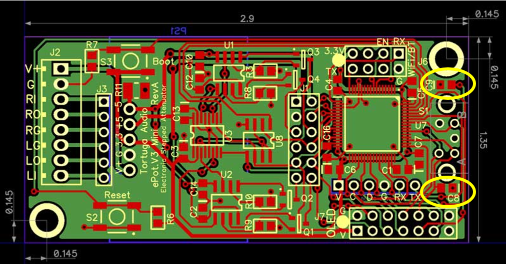
Errata: Please note that the two small capacitors C8 and C9 shown circled in yellow above should be removed from your Mini if present. They can either be snapped off or removed with a soldering iron. There’s minimal risk of damage to the board in removing these capacitors. Their presence is known to cause the Mini to halt operation when using the encoder.
Ambient conditions
The Mini was designed to operate within nominal room temperature conditions that are typical for home stereo equipment. LDRs are known to be temperature sensitive. Therefore large departures from nominal home room temperature conditions may cause the LDR attenuation to shift/left right or operate louder or quieter than usual at a given volume setting. Operating the Mini with an LDR attenuator module inside of equipment that gets very warm can still work but you may have to run calibration when the Mini has been warmed up and stabilized. We have not found this to be a problem within our own preamp products but the caution is valid.
Installing the Mini
The Mini is intended for panel mounted via the threaded bushing on the embedded encoder similar to a potentiometer or mechanical stepped attenuator. It’s also possible to chassis mount the Mini via the 2 mounting holes located in the opposite corners of the PCB using standoffs. You can also augment the panel mounting by adding a standoff to just the one PCB mounting hole in the rear of the board giving it additional rear support.
The installation steps for the Mini are as follows:
- Attach to panel – Insert the encoder shaft through a panel and securing it via a nut and washer. Please note that the front face of the encoder has a small extruded retaining pin that is intended to fit into a small hole on the back side of the panel to prevent the entire Mini assembly from turning. If you wish to keep/use this pin you will need to create a small hole/indentation in the panel for it to fit into. Otherwise you will need to snip this pin off to allow the encoder to properly seat itself squarely against the panel to which it’s mounted.
- Connect to power – Connect +12 VDC power to screw terminal J2.V+ and power ground to J2.G. Power voltage can range from 9-30 VDC.
- Connect audio signals – Connect the left and right channel inputs, outputs and signal grounds to the appropriately labeled J2 screw terminals. There are separate signal grounds (J2.RG & J2LG) for each channel for convenience so that the user can control where these signals ultimately meet at a common ground point.
- Connect IR receiver module (optional) – In order to operate the Mini via the Apple remote you must attach the IR receiver module to pins J7.IR, J7.V and J7.G. (see details on the IR receiver module elsewhere herein).
- Connect status LED (optional) – Connect the positive (long) leg of the status LED to J7.? and the negative (short) leg to J7.G. To enable the status LED you also need to place a jumper across pins J7.? and J7.?. The status LED and OLED display are mutually exclusive, i.e. you can install/use either but not both at the same time.
- Connect OLED display (optional) – Connect the OLED display to the J7 header using the 14 pin ribbon cable. Please note the the red stripe on the ribbon cable must align with the white dot on the J7 header on the Mini. Similarly the red stripe must align with the top edge of the OLED display’s interface board (the edge with the long horizontal row of pins) where the ribbon cable connects to the OLED’s J2 14 pin header. When using the OLED display the IR receiver module mounts/connects to the IR1 solder pads on the OLED interface board which in turn connect through to the Mini via the 14 pin ribbon cable. Please do NOT connect a separate rotary encoder to the OLED J3 header since this encoder will interfere with the Mini’s embedded encoder.
Power regulator board
The Mini has a separate dedicated power regulator board mounted to its underside that connects to the main board via a 5 pin header that runs parallel to the J3 audio socket. The regulator board is powered externally through the J2.V and J2.G screw terminals.
The power regulator board produces 3 different voltages each using low noise 2 stage regulation with a switching 1st stage followed by a linear 2nd stage. The voltages are as follows:
- +3.3V – primary voltage for powering the microcontroller, control DAC, encoder and display.
- +5V – positive split voltage for powering the current control op amps and also analog switches when a discrete attenuator module is installed
- -5V – complementary negative split voltage.
Some components on the power regulator board will feel hot to the touch when the Mini is powered up. This is normal.
Plug-in attenuation modules
The V3 requires a 2 channel plug-in attenuation module to function. The attenuation module plugs into the J1/J3 female headers on the V3 board. There are two types of plug-in attenuation modules available – LDR and discrete. Both types provide 2 channel stereo attenuation. The LDR type uses light dependent resistors and the discrete type uses pairs of discrete thin film surface mount resistors. Each of these attenuation module types are described in more detail below.
LDR attenuation module
The LDR attenuation module uses 2 pairs of LDRs with each pair controlling one channel of volume. Each LDR pair (channel) operates fully independent of the other. The LDR pairs are configured in a series/shunt arrangement that essentially emulates how a potentiometer controls volume. The resistance level of each LDR is independently controlled by a precision JFET op amp current controller which gets its set point from a 16 bit DAC controlled by a software driven 32 bit ARM microcontroller.

The performance characteristics (current vs. resistance) of each LDR is stored within an EEPROM memory chip on the attenuation module. The microcontroller reads the stored performance data of each LDR in real-time in order to set the target resistance level of each LDR as needed to achieve a given volume step. This process happens every time a volume step change occurs. The LDR attenuation module has 100 volume steps over a -60 to 0 dB control range. Each step change in volume is totally smooth and without any sonic artifacts related to control or step switching. In fact there’s no actual switching per se between each volume step, only a continuous analog transition from one set of resistance levels to the next.
The impedance of each LDR attenuation module is nominally fixed and must be specified at the time the Mini or LDR attenuation module is ordered. The impedance level is marked on the module within a circular white stick-on label which may be on bottom side of the module. The impedance level of each LDR module can in fact be changed by using an ePot.V3 Max which has built-in on board LDR calibration/programming, a feature not present on the Mini due to its smaller size.
Discrete attenuation module
The discrete attenuation module uses 7 pairs (+1) of discrete thin-film resistors per stereo channel for a total of 30 resistors per module. Thin-film resistors are typically composed of nickel-chromium metal deposited onto a ceramic base. These resistor pairs are arranged as a logarithmic set of individual switchable series/shunt attenuators with values of -0.5 dB, -1 dB, -2 dB, -4 dB, -8 dB, -16 dB and -32 dB. This is sometimes referred to as an R-2-R or ladder resistor set. This arrangements provides 127 attenuation steps of 0.5 dB per step over a control range of -63.5 to 0 dB. Individual resistor accuracy is typically 1% or better.

Each of the 14 discrete attenuation resistor pairs (7 per channel) are switched using single pole double throw analog switches that have fast, noiseless break-before-make characteristics. The result is smooth transitions between each of the 127 volume steps with no discernible sonic switching artifacts. The analog switches also have ultra-low distortion specifications of 0.004% THD.
Switching is controlled directly by V3’s 32 bit ARM microcontroller working through an output port expander chip located on each discrete attenuation module. Use of the expander chip greatly simplifies the control wiring making it possible to drive both types of attenuation modules from a single common control header.
The impedance of the discrete attenuation module is currently fixed at 60k. In the future we may offer discrete attenuation modules with other fixed impedance levels.
Changing attenuation module types
The ePot.V3 checks to determine which type of module is present each time it powers up. Therefore, it’s a simple matter to switch from one attenuation module type to the other. However, you must power down the V3 to swap out a module or change module type. Gently remove the current module and then gently insert the new module. Apply power, wait briefly for the unit to boot up, and then turn it on to use.
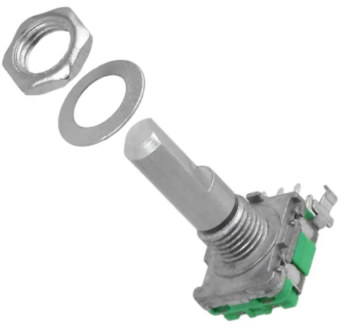
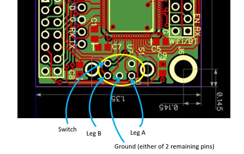
Encoder
The rotary encoder shown below is normally soldered directly into the Mini board and is to be used to mount the Mini through a front panel similar to any volume pot or stepped attenuator.
You can also request that the encoder be supplied loose in which case you will have to find an alternative way to mount the Mini itself and then wire the encoder to the Mini board using a 4 wire square pin cable. The encoder wiring diagram is shown below.
J1/J3 attenuation module headers
These two female headers accept the plug-in attenuation module. The attenuation module must be plugged into both headers simultaneously. The fit may be a bit tight and necessitate the gentle rocking of the module as it’s pressed in or removed. Care should be taken to ensure that the pins align properly with both headers before applying insertion pressure on the module. Care should also be taken to ensure the pins are not inadvertently offset and missing their respective sockets.
J1 audio header
J1 is a 6 position female header that routes the left and right channel input and output to and from the attenuation module. The 6 pins correspond to the same 6 audio input/output/ground pins described under the J2 screw terminal below.
J3 control header
J3 is a 12 position (2 x 6) female header that provides power and control signals to the attenuation module.
J2 screw terminal | power & audio
J2 is an 8 position screw terminal located on the opposite end of the board from the encoder. Power and audio both connect to the Mini through the J2 screw terminal header.
The J2 connections are as follows:
- J2.V – nominal +12 VDC power although the Mini is able to operate with 9-30 VDC supply.
- J2.G – power ground
- J2.RI – right channel audio input
- J2.RO – right channel audio output
- J2.RG – right channel audio ground
- J2.LG – left channel audio ground
- J2.LO – left channel audio output
- J2.LI – left channel audio input
The Mini typically draws under 150 ma without the OLED display and upwards of 300 ma with the display.
Each audio channel is entirely independent of the other within the Mini including the audio signal grounds.
J6 wifi/bluetooth header
J6 is an 8 position (2 x 4) pin header that’s intended to interface with a 3rd party WiFi or Bluetooth communications module. This feature remains in development and is not currently functional. The V3 will require a firmware update to enable this feature if/when it becomes available.
J7 OLED header
J7 is a 14 pin (2 x 7) header that carries the power and control signals for the OLED display, the IR receiver module, and the Status LED.
The J7 header can either be used for the Status LED & IR receiver or the OLED display but not both at the same time.
When an OLED display module is connected to the the 14 pin J7/OLED header, no other items can be connected to the J7 header. The OLED display module has a location to mount the IR receiver module directly on the OLED display interface board.
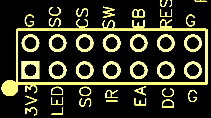
The header pins on the V3.Mini 14 pin J7/OLED header are NOT labeled on the circuit board due to space constraints. Note the white dot as a visual key reference which is present on the Mini. The J7 header with labels is shown above. Each pin is described briefly in the below going counter clockwise.
- J7.3V3 – power 3.3 volts
- J7.LED – power pin for optional panel LED
- J7.SO – SPI serial data output to OLED
- J7.IR – infrared receiver pulse input signal
- J7.EA – encoder leg A switch
- J7.DC – OLED data/command control output
- J7.G – ground
- J7.G – ground
- J7.RES – OLED reset control output
- J7.EB – encoder leg B switch
- J7.SW – encoder push button switch
- J7.CS – SPI serial chip select output to OLED
- J7.SC – SPI serial clock output to OLED
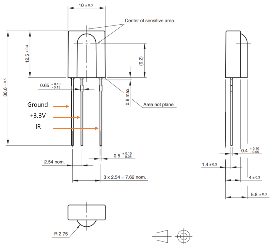
IR receiver module
When the OLED display is used the OLED display comes with the IR receiver module already mounted directly to the OLED display interface board.
Without the OLED display the IR receiver module must be connected to the following J7 pins. A 6 inch 3-wire square-pin cable is provided.
- Ground – J7.G (there are 3 available G pins for this on the J7 header)
- Power – J7.3V3
- Signal – J7.IR
The IR receiver module is a Vishay brand part number TSOP31138. It operates at a frequency of 38 kHz. Other IR receivers brands/models may also work but have not been tested by Tortuga Audio and in all cases must operate at the same frequency.
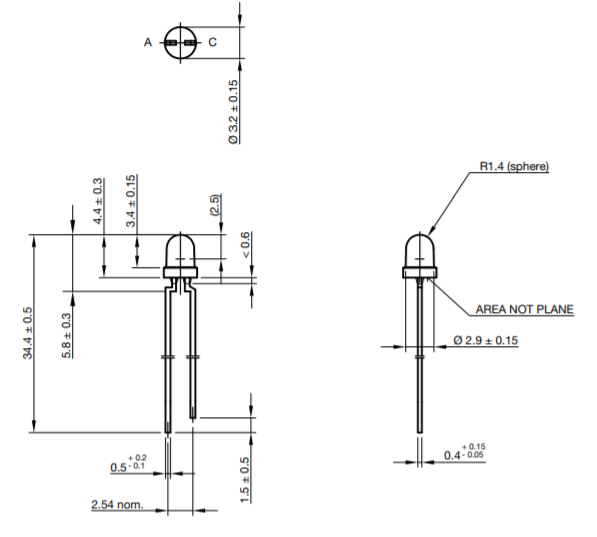
Status LED (optional)
The OLED display and the status LED are mutually exclusive in that that there is no way to connect a status LED to the Mini when an OLED display is plugged into the J7 header. If you are not using an OLED display you should connect a status LED to the J7 header so you can observe general status and responsiveness of the Mini to commands. A 6 inch 2-wire square-pin cable is provided for connecting the status LED to the J7 header.
The LED provided with the V3.Mini is a typical 3 mm size blue LED with typical dimensions shown below. You may wish to add a resistor to this circuit to tone down the brightness (limit the current) of the LED to suit your needs. This resistor is NOT included.
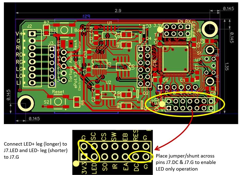
To enable proper operation with only a status LED, you must place a jumper across pin J7.DC and the adjacent J7.G pin as shown above and leave that jumper in place. This must be done prior to applying power to the board.
Then connect the status LED to the J7 header as follows:
- Short LED lead | Ground – J7.G (there are 3 available ground pins on the J7 header, one of which may already be occupied by the IR receiver module and the other by the status LED enabling jumper)
- Long LED lead | +voltage/control – J7.LED
J8 programming header
J8 is a 5 position pin header located parallel with and right above the J7 OLED header. J8 does not have a “J8” label on the PCB. The programming header is exactly what it sounds like – the header through which the Mini gets programmed either in the factory by Tortuga Audio or in the field by users.
The J8 pins going left to right are as follows:
- J8.V – +3.3 VDC power
- J8.C – programming serial clock
- J8.D – programming serial data
- J8.G – power ground
- J8.RX – UART #1 receive pin
- J2.TX – UART #1 transmit pin
Pins V.C.D.G are used by Tortuga Audio to install the original applications firmware. Interfacing with these pins requires specialized equipment and software and is not intended for use by the end user.
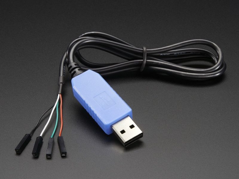
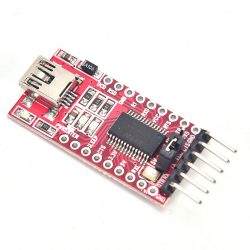
Pins V.G.RX.TX can be used by the end user to update the firmware using an application provided by Tortuga Audio. Connection to these 4 pins requires a special purpose USB-to-serial cable which are widely available online and typically cost between $10-15 or a USB-to-serial breakout boards that allow the user to accomplish the same thing for around $5 plus the cost of a standard USB Mini cable plus a square pin (4) jumper cable. Examples of each are shown below.
The detailed procedure for updating V3 firmware via the programming header is outside the scope of this document. Please refer to the V3 Firmware Updating documentation elsewhere in this system.
S1 Rotary encoder & pushbutton
S1 is an incremental encoder wherein a pair of internal switches open and close in different sequences depending on whether the encoder is rotated clockwise or counterclockwise. The microcontroller decodes these sequences to determine the direction of rotation. In addition, S1 has a 3rd integral pushbutton switch which is activated by pushing in the encoder shaft.
These encoder’s signals are used by the V3 microcontroller to turn the V3 on/off, control volume level, adjust channel balance, switch inputs (not available with the Mini), and mute/unmute the volume.
S2 Reset pushbutton
The S2 Reset pushbutton will reset the controller as if you cycled the power off and then on again. It resets the microcontroller. This is NOT a “factory reset” type of reset. It’s provided as a convenience but in practice is unlikely to be used very often. The S2 Reset button has a special purposed when used in conjunction with the S3 Boot pushbutton described below.
S3 Boot pushbutton
The S3 Boot pushbutton is used in conjunction with the S2 Reset pushbutton in order to place the V3 into “bootloader mode” for purposes of updating the V3’s firmware. By pressing the Boot pushbutton, then briefly also pressing/releasing the Reset pushbutton, and then finally releasing the Boot pushbutton as well, this places the V3 microcontroller into bootloader mode. When this is done with the V3 connected to a PC or a MAC equipped with the appropriate software, the software can then establish communication with the V3 via the J8 header and then update the V3’s firmware.
Firmware updating procedure
Information and procedure for updating V3 firmware via the J8 programming header is contained in a separate ePot.V3 Mini & Max firmware updating document.
Operation and control
Click this link for the documentation and control manual for both the Mini and the Max.
