
About this manual
This document provides commissioning information for a new or replacement ePot.V3 Max board. At the end of this section we also discuss steps for integrating the Max board with the SSPB.V2 Solid State Preamp Buffer board.
Ready to go as is
Each V3 Max board is shipped having already been put through a factory commissioning process that includes connecting a display, connecting a nominal 12 VDC source of power, loading the firmware, initializing certain data, running the board through a one-time factory pre-calibration process to normalize the characteristics of the LDR calibration circuit (the results of which are permanently stored in the board’s EEPROM memory), running the LDR attenuation module through 2 calibration cycles, and finally operating the Max with music to check that it’s functional.
Connect OLED display to J4
The OLED display connects to the J4 header via a 14 pin ribbon cable. In addition to the display itself, the OLED display assembly includes an encoder/pushbutton (attaches to the display interface board vis 4 pin encoder cable), as well as an infrared (IR) receiver module required for remote control operation. The IR module is permanently soldered to the display module interface board. Thus the J4 header includes not only the power, control, and data signals for the display itself, but also the 3 encoder signals, plus the 1 IR signal.
Please note that the red stripe on the OLED display ribbon cable must align with the white dot on the J4 header. The white dot is located at the end of the J4 header that has pins labeled J4.3V3 and J4.G.
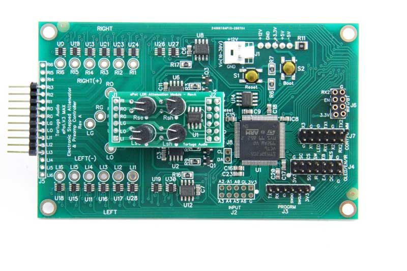
Connect power to J1
The Max runs on nominal 12 VDC power that connects to the J1 pin header. Please note the J1 pin polarity with the +12V pin and GND pins clearly labeled on the board on either side of the J1 pin header.
Connect input/output signals
The V3 Max has the ability to switch between 6 different stereo inputs resulting in a single attenuated stereo output signal. The Max has no “tape out” output signal of the unattenuated selected input.
Audio signal inputs and output can connect to the V3 Max through either the J5 header or individual input/output solder lugs (right inputs R1-6, left inputs L1-6, right/left outputs RO & LO, and right/left signal grounds RG & LG).
If only a single input is used, it must be connected to default left/right inputs L1 and R1 respectfully. We recommend connecting only a single input device initially. Once everything is working with only one input source connected, you can then proceed to connect additional input sources and testing that each input source switches in/out as expected.
Ground connections
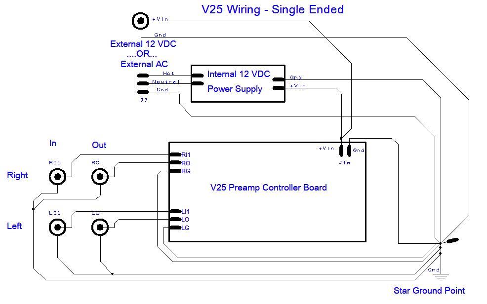
There’s no internal connection within the ePot.V3 Max between power supply ground connected at J1.Gnd and audio signal grounds connected at J2.RG and J2.LG. Nevertheless, power supply ground and audio signal grounds must be connected together external to the V3 Max in order for the LDR calibration procedure to work and also for the analog switches that switch between inputs to work properly.
Although not specific to the V3 board, the wiring diagram below for the earlier V25 model illustrates the highly recommended star grounding scheme. Ultimately ALL the input/output signal grounds plus the power supply ground need to be tied together at a single common star ground point internal to the preamp.
Once the display, power and inputs/outputs are connected, the next step is to apply power to the V3 Max and then turn it on.
Each time power is applied to the V3 Max, it goes through a brief initialization process during which it will briefly display an icon and/or product/company name that will then quickly fade to black. At this point the unit if ready to be turned on and used normally.
The Apple remote | pairing
If the V3 Max board was purchased with an Apple remote, that remote is already paired with your board and you can turn on the Max by pressing the Menu button on the remote. If you’re providing your own Apple remote, you have to first turn on the Max using the encoder via a brief push/release of the encoder push button. Once turned on, you then have to “pair” your remote with the Max. The Apple remote pairing process is described here. Once paired, you can use the remote going forward instead of the encoder.
Turn it on
The Max can be turned on with either the encoder push button (via a brief push/release) or the Apple remote by pressing the Menu button. An icon and/or product/company name that will briefly fade into view on the display, and then be replaced by the default volume control action view which will set the volume to the same volume level it was at when it was last turned on. The nominal initial factory volume setting is step 30 which should be loud enough to hear and not so loud that you’ll need to immediately turn it down.
Interfacing with SSPB.V2 Solid State Buffer
Detailed information on the SSPB.V2 can be found via this link. The information below provides additional information on interfacing the V3 Max with the SSPB.V2.
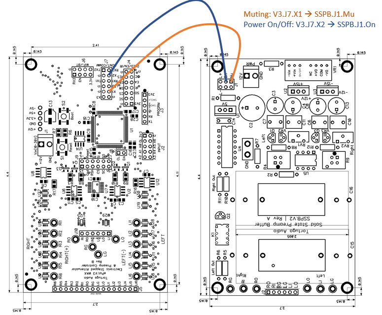
When the SSPB.V2 solid state buffer is used together with the Max, 2 control signals must be connected from the Max to the buffer board. Those control signals are Muting and Power as shown in the image below.
The Muting signal runs from the V3.J7.X1 pin to the SSPB.J1.Mu pin. This signal controls the muting relay on the SPPB buffer. The Power signal runs from the V3.J7.X2 pin to the SSPB.V1.On pin. This signal turns the SSPB’s voltage regulator (VR1) on and off. Please note that when turned on via the Power signal, there’s a 3-5 second delay before the SSPB is enabled. This delay is programmed into the SSPB and cannot be overridden by the V3.
Please be aware that earlier versions of V3 Max firmware used the V3.J7.X3 pin instead of the V3.J7.X1 pin for Muting as shown in the diagram below. If the X1 pin isn’t active or responding properly on your V3 Max, please try the X3 pin as an alternative.
Also please note that as of firmware version 3.2.1 and later, that the user may select between using pins X1 or X3 for the Muting signal via the control menu.
Make sure to first remove any existing jumpers/shunts from the J1 header on the buffer board before connecting these 2 control wires.
The ground connection to the SSPB board can be made at either the SSPB.PWR.GND power input pin, or, at the SSPB.J2.RG & LG pins. Both ground connections connect into a common ground internal to the SSPB board. Connect ground to one or the other, but NOT BOTH! Connecting ground to both locations invites an internal ground loop and commensurate ground loop hum.
Final LDR calibration
Once you have the V3 running and behaving normally, we recommend that you put the board through a calibration cycle. Nothing you did during commissioning should impact the calibration results already stored on the Max board from when the Max was originally commissioned in the factory. However, it’s always a good idea to confirm that everything, including the calibration process, is fully functional as a final step in installing and commissioning the V3 Max.
Diagnosing problems
If you run into any problems, we recommend that you:
- DO NOT automatically conclude the Max board is faulty (yes, it could be faulty but chances are it’s fine – double check everything else first)
- DO NOT run the Reset command from the control menu thinking this will put everything back to normal and solve your problem (it probably won’t since Reset mostly erases all your LDR calibration data)
- ALWAYS first test the Max board by itself before connecting it to the SSPB.V2 buffer board and testing them together
