
About this manual
This hardware manual describes the physical hardware and installation of the ePot.V3 Max (the “V3” or “Max” ) electronic stepped attenuator & remote controlled preamp controller. A discussion on the operation and control of the Max board is available separately here.
What is the ePot.V3 Max?
The ePot.V3 Max is a high resolution chassis mounted electronic stepped attenuator for the DIYer, audio designer or OEM who is looking for exceptional sonic performance in a stepped attenuator (volume control) in addition to being a software driven preamp controller that includes input switching, remote control and has a menu driven interactive high contrast OLED display interface.
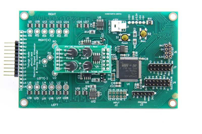
The V3 Max comes with a plug-in LDR (light dependent resistor) attenuation module by default but you can opt for a discrete resistor attenuation module. The different module types are interchangeable.
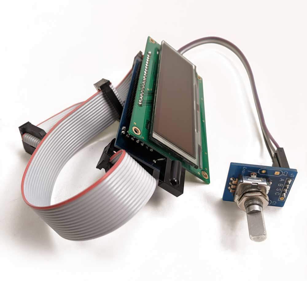
The graphic OLED Display Module shown below (sold separately) integrates with the V3 to provides an easy and intuitive user control experience through an interactive menu driven control interface designed around the 7-button Apple remote. The OLED Display Module incudes the display itself, an installed IR receiver module, an encoder module plus all necessary cables.
Hardware Versions
The V3 Max is now on its second hardware iteration with Version B released as of May 2021. Hardware design iterations are the result of ongoing development work that retain the core board design, interfaces and dimensions while incorporating improvements that delivers a more robust product with even better sonic performance.
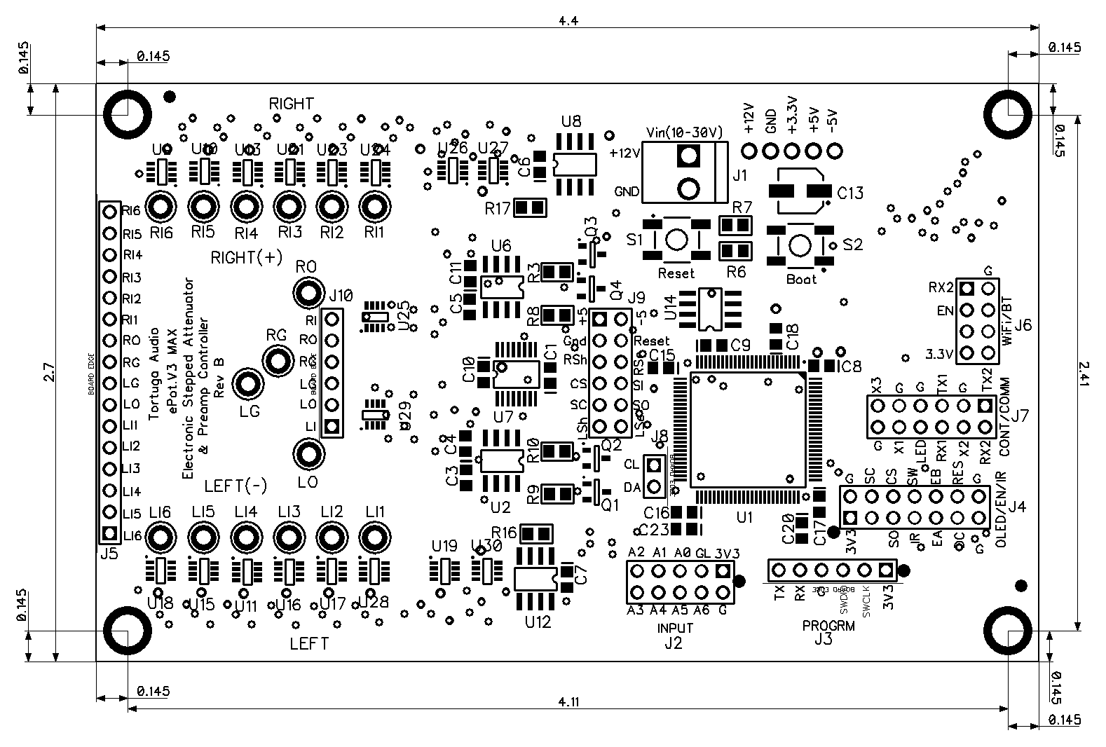
The Rev B hardware changes are dominated by a fully redesigned power conversion board located on the underside of the primary board. The Rev C hardware changes eliminate the separate power board and move those components on to the main board.
All changes are summarized in the table below.
| V3 Max Version | Rev A | Rev B | Rev C |
|---|---|---|---|
| Release Date | Sept 2020 | May 2021 | 1Q2022 |
| DC-DC power board | Based on a design by Texas Instruments | Simpler, more robust, more efficient, quieter design by Tortuga Audio | Same design as Rev B but power board eliminated and parts moved on to main board. |
| Minimum load resistor | Negative 5 volt minimum load resistor for stability | Deleted, no longer required. | same as Rev B |
| 3.3 volt power capacitor | Small - ceramic. | Added larger electrolytic storage capacitor to ensure stable supply during any transients | same as Rev B |
| Mono mode | Yes | No - removed the mono mode switch to eliminate any possibility of channel cross talk during normal operation | same as Rev B |
| Part Changes | Baseline | Removed: U31 & R11 Relocated: S1, S2, R6 & R7 Added: C13 Replaced: Power board (located on underside of main board) | Deleted the S1/S2 boot/reset switches |
Notes: (1) There are no relays in the signal path during normal operation
The parts for both the Rev A and Rev B boards are shown in the two diagrams below.
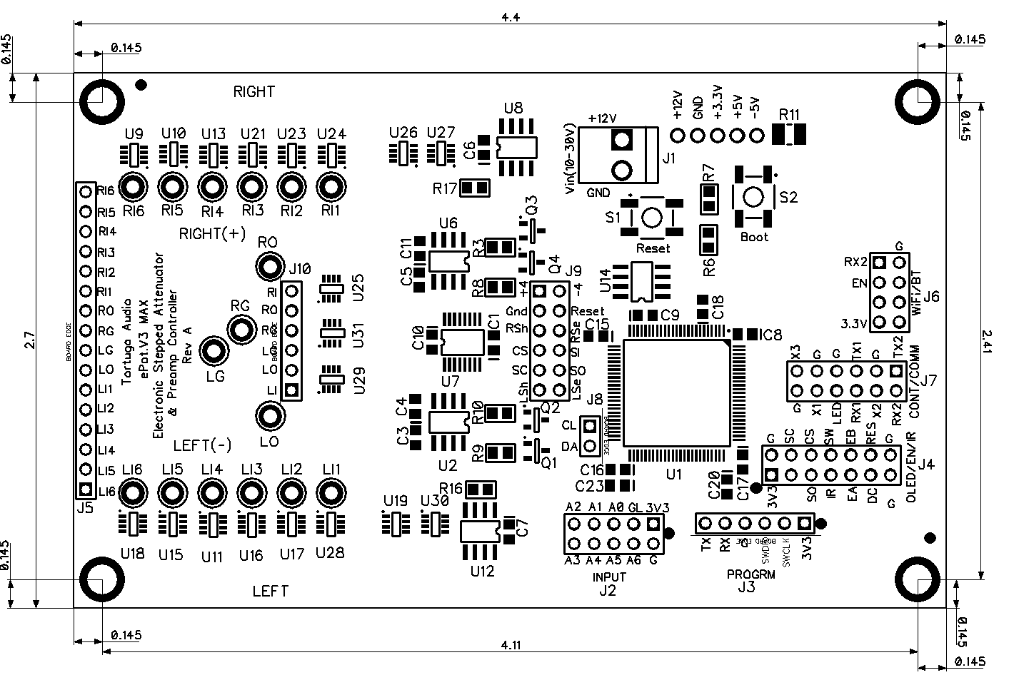
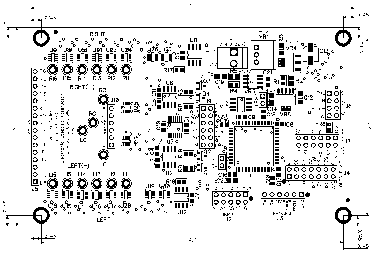
Physical dimensions
The Max board is 2.7 inches wide by 4.4 inches long. The overall depth is slightly greater than 1 inch but we recommend allocating 1.5 inches of vertical space along the length of the Max. These dimensions are the same for all V3 Max hardware versions.
Comparison of the ePot.V3 Max vs. Mini
The Max and Mini are based on the same core hardware design and run essentially the same firmware.
The 3 most significant differences are that: 1) the Mini has no input switching (single input only); 2) and the Mini does not have built-in LDR calibration; and 3) the Max must be chassis mounted while the Mini can be mounted directly into a front panel as would a conventional potentiometer or stepped attenuator.
Here is a comprehensive comparison showing similarities and differences.
| ePot.V3 Max | ePot.V3 Mini | |
|---|---|---|
| Size | 2.7 x 4.4 inch | 1.35 x 2.9 inch (67% smaller) |
| Input Switching | Yes - built-in switching between 6 stereo input channels | No switching - single stereo channel |
| Mounting | Chassis mounted w/ standoffs (not included) | Panel mounted via integral board mounted encoder (like a potentiometer) |
| Balanced Audio | Yes - requires 2 separate boards and a 2 wire serial data link | No - single-ended only |
| LDR Module Calibration | Yes - built-in | No - Uses replaceable plug-in LDR module or you can use a separate ePot.V3 Max to calibrate any LDR module for any Mini |
| Attenuation Type | Plug-in LDR module | Same |
| Controls | * Rotary encoder (externally mounted) * Apple remote control (infrared) | Same except the rotary encoder is mounted directly to the Mini board by default. If you wish you can order a Mini without the encoder installed. This way you can mount the encoder in the front panel and locate the Mini board itself elsewhere. |
| Display | * Status LED * Optional OLED Display (with encoder and IR receiver interface) | Same except OLED and Status LED are mutually exclusive since they both use the same header |
| Auxiliary Control Header | 6 bit signal for controlling external devices | No |
| WiFi Module | Future capability | Same |
| Microcontroller | 100 pin STM32F2 microcontroller | 64 pin STM32F2 microcontroller |
| Firmware Update | Yes - via USB to 2-wire serial UART link | Same |
| Remote Control | Yes - via Apple remote and externally mounted IR receiver | Same |
| Manual Control | Yes - via rotary encoder (externally mounted) | Yes - via integral board mounted rotary encoder |
Ambient conditions
The ePot.V3 was designed to operate within nominal room temperature conditions that are typical for home stereo equipment. LDRs are known to be temperature sensitive. Therefore large departures from nominal home room temperature conditions may cause the LDR attenuation module to operate poorly. Operating the V3 with an LDR attenuator module inside of equipment that gets very warm may still work but you may have to run calibration when the Mini has been warmed up. We have not found this to be a problem within our own preamp products but the caution is valid.
Power regulator board
The ePot.V3 Max has a separate dedicated power regulator board mounted to its underside that connects to the main board via a 5 pin header. The power board design was updated as part of the version B release of the ePot.V3 Max. Later version A production boards also included the updated power board and can be identified via the OLED display “Version” menu item as a Max Version A1.
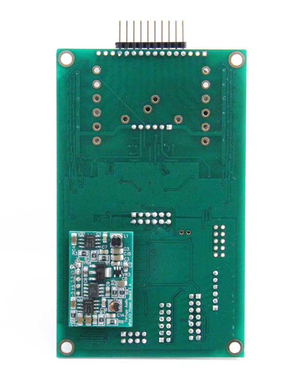
The power regulator board produces 3 different voltages each using low noise 2 stage regulation with a switching 1st stage followed by a linear 2nd stage. The voltages are as follows:
- +3.3V – primary voltage for powering the microcontroller, control DAC, encoder and display.
- +4.8V – positive split voltage for powering the current control op amps and also analog switches when a discrete attenuator module is installed
- -4.8V – complementary negative split voltage.
Some components on the power regulator board will feel hot to the touch when the Mini is powered up. This is normal.
Plug-in attenuation modules
The V3 requires a 2 channel plug-in attenuation module to function. The attenuation module plugs into the J1/J3 female headers on the V3 board. There are two types of plug-in attenuation modules available – LDR and discrete. Both types provide 2 channel stereo attenuation. The LDR type uses light dependent resistors and the discrete type uses pairs of discrete thin film surface mount resistors. Each of these attenuation module types are described in more detail below.
LDR attenuation module
The LDR attenuation module uses 2 pairs of LDRs with each pair controlling one channel of volume. Each LDR pair (channel) operates fully independent of the other. The LDR pairs are configured in a series/shunt arrangement that essentially emulates how a potentiometer controls volume. The resistance level of each LDR is independently controlled by a precision JFET op amp current controller which gets its set point from a 16 bit DAC controlled by a software driven 32 bit ARM microcontroller.
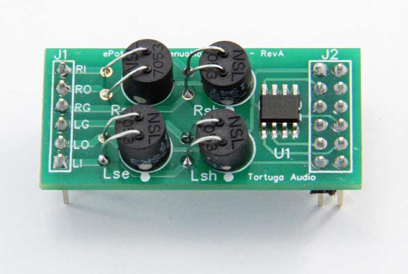
The performance characteristics (current vs. resistance) of each LDR is stored within an EEPROM memory chip on the attenuation module. The microcontroller reads the stored performance data of each LDR in real-time in order to set the target resistance level of each LDR as needed to achieve a given volume step. This process happens every time a volume step change occurs. The LDR attenuation module has 100 volume steps over a -60 to 0 dB control range. Each step change in volume is totally smooth and without any sonic artifacts related to control or step switching. In fact there’s no actual switching per se between each volume step, only a continuous analog transition from one set of resistance levels to the next.
The impedance of each LDR attenuation module is nominally fixed and must be specified at the time the Mini or LDR attenuation module is ordered. The impedance level is marked on the module within a circular white stick-on label which may be on bottom side of the module. The impedance level of each LDR module can in fact be changed by using an ePot.V3 Max which has built-in on board LDR calibration/programming, a feature not present on the Mini due to its smaller size.
Discrete attenuation module
The discrete attenuation module uses 7 pairs (+1) of discrete thin-film resistors per stereo channel for a total of 30 resistors per module. Thin-film resistors are typically composed of nickel-chromium metal deposited onto a ceramic base. These resistor pairs are arranged as a logarithmic set of individual switchable series/shunt attenuators with values of -0.5 dB, -1 dB, -2 dB, -4 dB, -8 dB, -16 dB and -32 dB. This is sometimes referred to as an R-2-R or ladder resistor set. This arrangements provides 127 attenuation steps of 0.5 dB per step over a control range of -63.5 to 0 dB. Individual resistor accuracy is typically 1% or better.
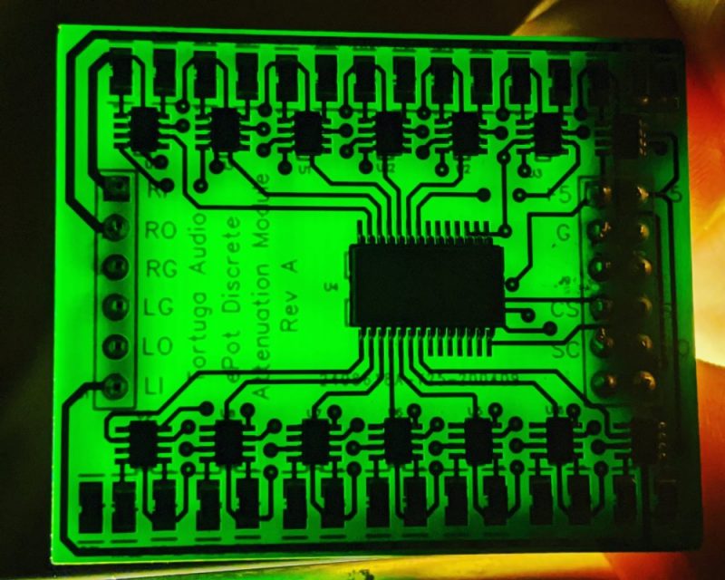
Each of the 14 discrete attenuation resistor pairs (7 per channel) are switched using single pole double throw analog switches that have fast, noiseless break-before-make characteristics. The result is smooth transitions between each of the 127 volume steps with no discernible sonic switching artifacts. The analog switches also have ultra-low distortion specifications of 0.004% THD.
Switching is controlled directly by V3’s 32 bit ARM microcontroller working through an output port expander chip located on each discrete attenuation module. Use of the expander chip greatly simplifies the control wiring making it possible to drive both types of attenuation modules from a single common control header.
The impedance of the discrete attenuation module is currently fixed at 60k. In the future we may offer discrete attenuation modules with other fixed impedance levels.
Changing attenuation module types
The ePot.V3 checks to determine which type of module is present each time it powers up. Therefore, it’s a simple matter to switch from one attenuation module type to the other. However, you must power down the V3 to swap out a module or change module type. Gently remove the current module and then gently insert the new module. Apply power, wait briefly for the unit to boot up, and then turn it on to use.
Chassis mounting
The Max is a chassis mounted board that is typically mounted horizontally on standoffs but can also be mounted vertically on its side (mounting hardware not included). In addition to installing the Max itself, a separate status LED and/or an OLED display module, IR receiver module, and rotary encoder will typically need to be installed in the front panel of an enclosure.
We recommend minimum 1/2 inch tall standoffs to ensure good clearance and airflow around the power board on the underside of the the Max board. Ideally the audio connection header end of the Max will be oriented towards the rear of chassis to minimize audio signal runs while the other end of the Max is oriented towards the chassis’s front panel.
J1 power connector
J1 is a 2-pin 0.156 inch (3.98 mm) male power connector. It accepts a matching plug with a friction lock tab with wiring connected to the plug via crimp pins that slip and lock into the plug housing. The plug and pins are supplied with the Max.
Care must be taken to ensure proper polarity since reversing polarity is likely to damage the power supply board and require the Max be replaced.
The Max can operate on unregulated DC power sources between 9 and 30 V DC. Current demand is modest (well under 0.5 A).
J2 auxiliary header (future use)
J2 is an unpopulated 10 position (2×5 pin) header designated for future use. J3 provides 3.3V power and ground plus 8 additional input/output control signals labeled A0-A6 plus GL.
J3 programming header
J3 is a 5 position pin header. The programming header is exactly what it sounds like – the header through which the Max gets programmed either in the factory by Tortuga Audio or in the field by users.
The J3 pins going right to left are as follows:
- J3.V – +3.3 VDC power
- J3.C – programming serial clock
- J3.D – programming serial data
- J3.G – power ground
- J3.RX – UART #1 receive pin
- J3.TX – UART #1 transmit pin
Pins V.C.D.G are used by Tortuga Audio to install the original applications firmware. Interfacing with these pins requires specialized equipment and software and is not intended for use by the end user.
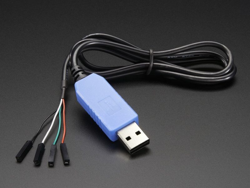
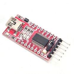
Pins V.G.RX.TX can be used by the end user to update the firmware using an application provided by Tortuga Audio. Connection to these 4 pins requires a special purpose USB-to-serial cable which are widely available online and typically cost between $10-15 or a USB-to-serial breakout boards that allow the user to accomplish the same thing for around $5 plus the cost of a standard USB Mini cable plus a square pin (4) jumper cable. Examples of each are shown below.
The detailed procedure for updating V3 firmware via the programming header is outside the scope of this document. Please refer to the V3 Firmware Updating documentation elsewhere in this system.
J4 OLED header
J4 is a 14 pin (2 x 7) header that carries the power and control signals for the OLED display, the IR receiver module, and the rotary encoder.
When the OLED display ribbon cable is plugged into the J4 header, the IR receiver module and encoder can no longer connect directly to the J4 header and are instead mounted on or connected to the OLED display interface board. The IR/encoder signals run through the OLED ribbon cable along with the OLED power and control signals.
When no OLED display is present, the IR receiver module must be connected to the J4 pins marked [IR] and the encoder must be connected to the pins marked [ENCODER] in the list below.
The J4 pins are labeled as follows in the clockwise direction:
- J4.3V3 – 3.3 V DC power [IR.V]
- J4.G – ground [IR.G]
- J4.SC – SPI clock
- J4.CS – SPI OLED chip select
- J4.SW – encoder switch [ENCODER.SW]
- J4.EB – encoder leg B [ENCODER.B]
- J4.RES – OLED reset
- J4.G – ground [ENCODER]
- J4.G – ground
- J4.DC – OLED data/command select
- J4.EA – encoder leg A [ENCODER.A]
- J4.IR – IR receiver signal [IR.IR]
- J4.SO – SPI data
- J4.__ – no connection
J5 audio header & solder pads
Audio input, output and signal grounds to the Max board can be connected via either the J5 16 position 0.1 inch pitch header or a separate collection of larger solder pads.
The J5 header is unpopulated and accepts direct wire soldering or the use of either male or female pin headers/sockets (not provided).
These connections are identified as follows:
- RI1-6 – right inputs #1 through #6
- RO – right output
- RG – right signal ground
- LG – left signal ground
- LO – left output
- LI1-6 – left inputs #1 through #6
The left and right signal grounds are fully independent and DO NOT connect within the Max board to the power ground.
J6 wifi/bluetooth header (future use)
J6 is 2×4 pin header designated for use with an attached wifi or bluetooth module. This is currently not implemented and will require a firmware update if/when this feature becomes available.
The pins are labeled clockwise as follows:
- J6.3.3V – 3.3V power
- J6._ – no connection
- J6.EN – device enable
- J6.RX2 – UART #2 receive
- J6.G – ground
- J6._ – no connection
- J6._ – no connection
- J6.TX2 – UART #2 transmit
J7 control & communication header
J7 is a combined control and communications header. It incorporates 2 independent sets of UART serial communications ports plus 4 additional control input or output pins. These are all 3.3V TTL type microcontroller signals and should NOT be relied on to source or sink more than a few milliamps of current.
The pins are labeled clockwise as follows:
- J7.TX2 – UART #2 transmit pin
- J7.RX2 – UART #2 receive pin
- J7.X2 – extra control pin #2
- J7.RX1 – UART #1 receive pin
- J7.LED – status LED output pin
- J7.X1 – Mute Out | Changes state when the preamp controller mutes/unmutes. Can be used to mute/switch an external device in coordination with the Max muting function.
- J7.G – ground
- J7.X3 – Trigger Out | Changes state when the preamp controller is turned on and off. Can be used to switch an external device that needs to turn on/off in coordination with the Max.
- J7.G – ground
- J7.G – ground
- J7.TX1 – UART #1 transmit pin
- J7.G – ground
J8 I2C comunication header (future use)
J8 is an unpopulated 2 pin header for I2C serial communications. It is currently not implemented and may be used in the future.
J9/J10 attenuation module sockets
These two pin sockets accept the plug-in attenuation module. The attenuation module must be plugged into both headers simultaneously. The fit may be a bit tight and necessitate the gentle rocking of the module as it’s pressed in or removed. Care should be taken to ensure that the pins align properly with both sockets before applying insertion pressure on the module. Care should also be taken to ensure the pins are not inadvertently offset and missing their respective sockets.
J10 audio socket
J1 is a single row 6 position pin socket that routes the left and right channel input, output and signal ground to and from the attenuation module. The 6 pins correspond to the same 6 audio input/output/ground pins as the J5 screw terminal.
J9 control socket
J3 is a double row 12 position (2 x 6) pin socket that provides power and control signals to the attenuation module.
S1 Reset pushbutton
The S1 Reset pushbutton will reset the controller as if you cycled the power off and then on again. It resets the microcontroller. This is NOT a “factory reset” type of reset. It’s provided as a convenience but in practice is unlikely to be used very often. The S1 Reset button has a special purposed when used in conjunction with the S2 Boot pushbutton described below.
Only Rev A and B boards has an S1 reset button.
S2 Boot pushbutton
The S2 Boot pushbutton is used in conjunction with the S1 Reset pushbutton in order to place the V3 into “bootloader mode” for purposes of updating the V3’s firmware. By pressing the Boot pushbutton, then briefly also pressing/releasing the Reset pushbutton, and then finally releasing the Boot pushbutton as well, this places the V3 microcontroller into bootloader mode. When this is done with the V3 connected to a PC or a MAC equipped with the appropriate software, the software can then establish communication with the V3 via the J8 header and then update the V3’s firmware.
Only Rev A and B boards has an S2 reset button.
Firmware updating procedure
The firmware updating procedure for both the Max and Mini can be found in a dedicated document section entitled ePot.V3 Max and Mini Firmware Updating.
Operation and control
The detailed procedures for operating and controlling the ePot.V3 models is available here in a separate document.
