Overview
As of June 2021 and release of firmware version 2.2.3 or above, the V3 Max electronic stepped attenuator & preamp controller is capable of balanced audio attenuation using a pair of Max boards.
Wiring for balanced audio attenuation can be challenging for the simple reason that it’s more complex than wiring single-ended RCA audio signals. It’s easy to make mistakes so before diving in with wiring your V3 Max boards for balanced audio, we strongly recommend you study the diagram below carefully. Also, if you’re not familiar with the concept of 3-pin balanced wiring & connectors, please also review the section at the bottom of this article.
Finally, in case you had prior experience with our V25 series controllers, please note that the balanced audio wiring for the V3 series controller is different than the V25 controller.
V3 Max balanced wiring
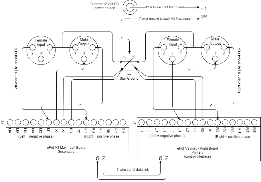
A key starting point for balanced audio attenuation is to recognize that two (2) V3 Max boards are required for balanced audio attenuation/control. The reason for this is simple. Each V3 Max board is a 2 channel stereo attenuator. However, with balanced audio you are dealing with 4 channels; right + & – and left + & – phases. The 2 right channel phases are handled by the Primary V3 Max board while the 2 left channel phases are handled by the Secondary V3 Max board.
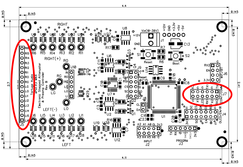
The V3 Max balanced wiring is shown schematically in the diagrams below. References are made to the J5 and J7 headers which are circled in red in the V3 Max board layout shown above.
While the Max can accommodate up to 6 inputs, only 1 set of inputs is shown in the diagram below to avoid making the diagram overly busy/complex.
All the “rules” for wiring the V3 Max for balanced audio are summarized as follows:
Two Max Boards – Two V3 Max boards are required for balanced audio attenuation (the V3 Mini does not currently handle balanced audio)
Right is Primary – The right channel board is designated as the Primary board
Left is Secondary – The left channel board is designated as the Secondary board
Primary handles all user interface – The Primary board handles all the control interfaces such as remote control, encoder and display. There’s no direct control interface or human interaction with the Secondary board.
2-wire serial data link – The Primary and Secondary boards communicate with each other via a 2 wire serial data link. The Primary board is responsible for communicating to, and synchronizing with, the Secondary board via the data link.
Any V3 Max board can be the Primary or the Secondary board – A V3 Max board is designated as Primary or Secondary by virtue of how the 2 wire serial data links are connected between the two boards (more details on this below)
R are positive phase | L are negative phase – Within each board the right “R” labeled input/output pins handle the positive (+) phase while the left “L” labeled input/output pins handle the negative (-) phase. This is a arbitrary designation but we recommend you follow this to avoid confusion and to help with any trouble-shooting.
Star ground – All grounds (including the pin 1’s) get wired to a single common “star ground” point somewhere within the enclosure. This may not be standard practice with all balanced audio gear but we have found this approach to work best when using Tortuga Audio attenuators/controllers.
Power ground – The power ground must also be tied to the “star ground” in order for everything to work properly. This is especially important to ensure that the LDR calibration feature of the V3 Max works properly.
2-wire serial data link
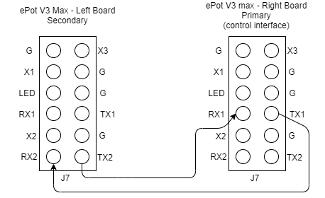
The designation of which Max board is the Primary and which is the Secondary is solely determined by how the 2-wire serial data link is connected between the two boards. The Primary board connects the J7.TX1 and J7.RX1 pins to the Secondary board’s J7.RX2 and J7.TX2 pins respectively. This is shown in the diagram below. Once these 2 connections are made, both Max boards must be powered off and then powered on again to assert this configuration.
3 pin XLR wiring overview
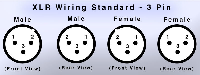
Balanced audio signals typically use XLR type 3-pin connections. XLR wiring is unavoidably more complex than single-ended RCA.
With single-ended audio you have only the signal itself and the the signal ground reference. However, with balanced audio you have 2 audio signals (pins #2 and #3) plus a 3rd shield/ground pin (pin #1). The 2 audio signals are identical except that they are 180 degrees out of phase with respect to each other. Usually pin #2 carries the positive (+) phase while pin #3 carries the negative (-) phase.
Additional complexity comes from the fact that the physical position of pins #1 and #2 within the XLR plugs & sockets are reversed depending on whether you are wiring a female/input or a male/output connector.
Last, but not least, XLR connector pin diagrams sometimes show the pins in a front view (the way humans see the finished product) while others show the pins in a rear view (as seen from the perspective of the wire going into the XLR connector).
For purposes of preserving your sanity and ours, this article refers to the front view only – the view you see when looking at a panel with XLR sockets facing you or when looking into the business end of an XLR jack at the end of an XLR cable.