
A brief history
The 7-segment LED display assembly (the DM1) was released at the same time as the V2 preamp controller. It was the only display assembly for the V2 series preamp controller. Version A of the subsequent V25 preamp controller also used the same 7 segment LED display. The V25 RevA controller board had a pin header dedicated to the 7-segment LED display. It also had a header dedicated to the newer OLED display. The OLED display was released approximately 6 months after the V25 came out once the OLED driver/firmware was ready. Subsequent revisions B and C to the V25 board eliminated the 7-segment display interface header however the signals needed for the 7-segment display are still available from the 14 pin OLED interface.
Display assembly
A typical 7-segment display assembly includes a pair of dual display modules as shown below. A pair of modules allow for the separate display of the left and right channel volume levels along with other relevant information. Each module is limited to displaying only 2 numerical digits which greatly limits their use in comparison to more recent display technology such as graphical OLED displays.
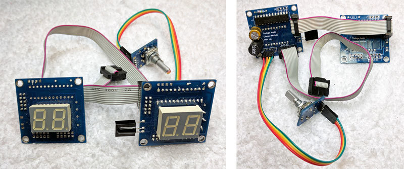
The 7-segment display assembly is composed of a pair of circuit board with each having a 2-digit 7-segment LED component. Each board is referred to as a “display module”. The right channel module is designated the primary module and is populated with a display chip, has a 4-pin header for connecting the encoder, and solder pads for attaching the 3-pin infrared (“IR”) receiver module. The main ribbon cable runs from the primary module to a V2 or V25 preamp controller board (not shown above). A second shorter ribbon cable connects the primary display module to the secondary (left channel) display module. The secondary display module has no other components except for the 2-digit 7-segment component.
Each display module uses a 2-digit, 0.58″ tall, 7-segment LED type display component. Each of the 7 LED segments are individually turned on and off by a driver chip and together are capable of showing a numbers between 0 and 9 plus a period (dot) next to each digit. Being a 2-digit LED component allows each 7-segment module to display a number between 0 and 99.
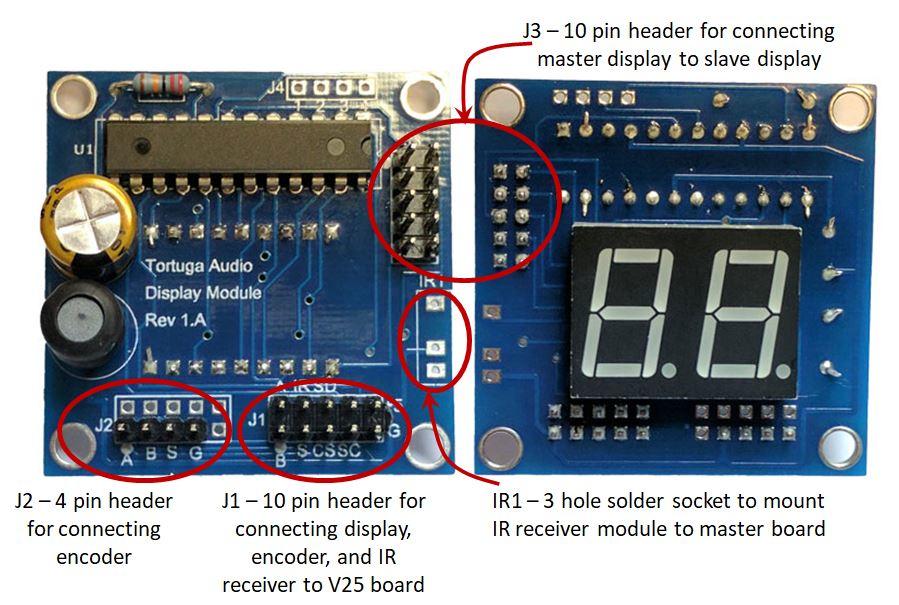
The picture above show both sides of a primary 7-segment display module. The secondary module (not shown) has an identical 2 digit 7-segment LED but is missing a control chip and other primary components is instead driven by the primary module. The primary board has a special purpose 7-segment driver chip. The preamp controller board (V25 or V3 et. al. ) communicates with the LED display driver chip via an SPI serial data link connected to the 10-pin J1 header on the primary display module. The encoder connects via the 4-wire J2 header.
