
Stepped attenuator and preamp controller
The V25 is a digitally controlled, analog 2 channel stepped attenuator and preamp controller. Unlike most audio attenuation technology the V25 utilizes light dependent resistors (LDRs) for both attenuation and in lieu of conventional relays for input switching.
The V25 Preamp Controller (Rev A) was released in April, 2017 and subsequently 2 minor hardware revisions have been made.
Noteworthy features of the V25 include the following:
- Smooth 100 steps of attenuation over a 60 dB range at ~0.6 dB per step
- Input switching of up to 6 stero inputs
- 2 units can be combined for balanced audo
- Fully remote controllable via simple infrared Apple remote
- Manually controllable via rotary encoder/pushbutton with limitations
- Smooth muting
- Left/right channel balance
- LDRs employed both for attenuation and input switching
- Built-in self-contained LDR calibration of replaceable plug-in LDR modules
- High contrast 256×64 bit white-on-black OLED display with interactive menu structure
The V25 board is shown below with annotation of the key components and control interface points. Please refer to V25 Specifications section for more detail.
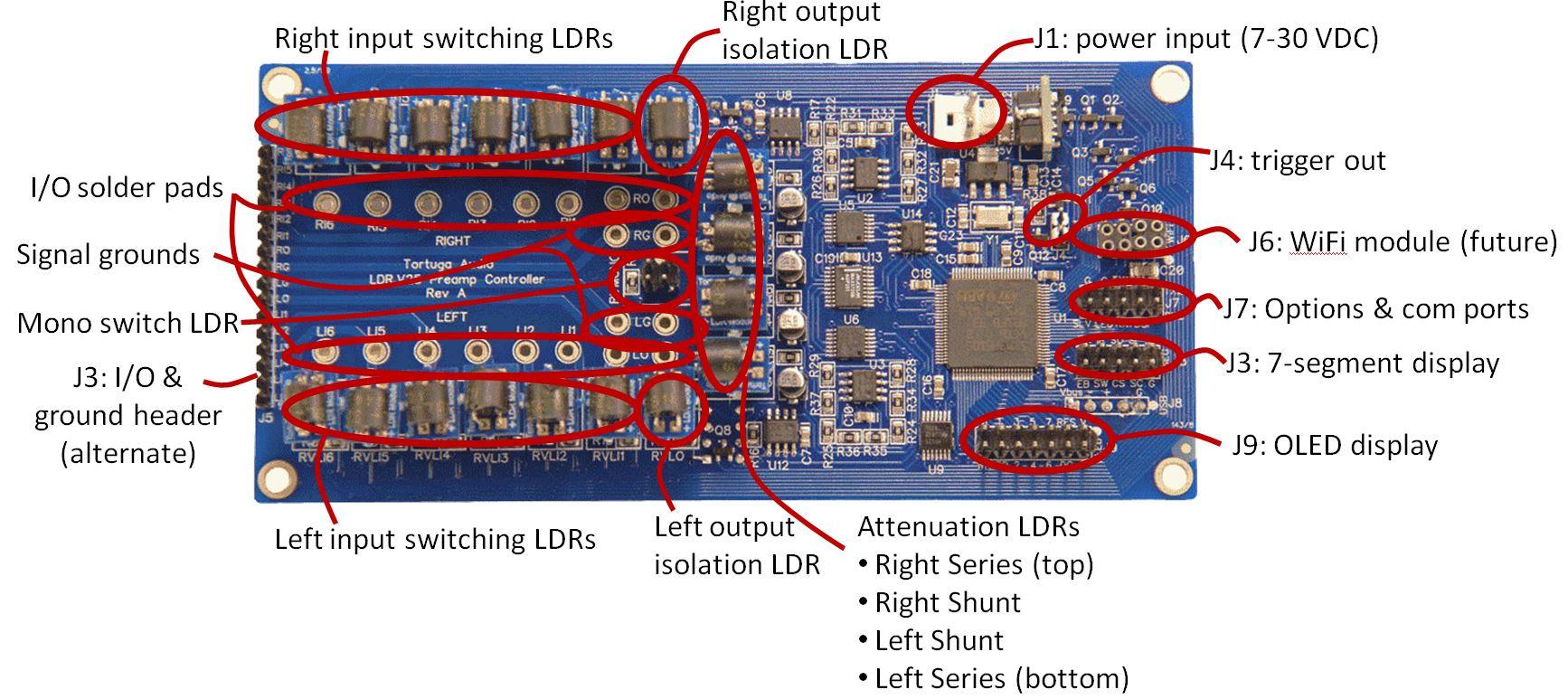
The V25 is powered by a nominal 12V supply (not included) which is coverted to both 5V and 3.3V for use within the board. The V25 is driven by an embedded ARM microcontroller. Control interfaces include a remote control infrared receiver, UART serial communication ports, trigger outputs, USB port, OLED display, and most significantly the LDRs themselves which contain light emitting diodes to modulate their variable resistance.
The V25 is classified as a unity gain “passive” preamp device with no active amplification or buffering of the audio signal. That means there is no direct connection to, or manipulation of, the audio signal by a power supply. Despite the sophistication of the V25 design, each audio channel signal “sees” only a voltage divider composed of 2 LDRs in a classic series/shunt L-Pad configuration that emulates a potentiometer.
Hardware versions
The 3 hardware versions of the V25 board include A, B and C with A being the original board as shown above. The version letter is printed on the V25 board on the left side under the name of the board.
The differences between these versions relate solely to the display interfaces and the USB interface. These differences are summarized in the table below. All 3 versions utilize the same firmware which recognizes these differences.
| Criteria | Version A | Version B | Version C |
|---|---|---|---|
| 7 segment display | Yes | J3 header | Yes | J3 header | Yes | via individual signals from OLED J9 header |
| OLED display interface (J9) | Yes | parallel | Yes | serial SPI | Yes | serial SPI |
| Serial (SPI) interface voltage to 7 segment display header (J3) | 5V | 3.3V | N/A |
| USB header 5V VBus pin powerered by board | No | Yes | Yes |
Dual board balanced audio
Balanced stereo audio is a minimal example of using the V25 in a multi-channel audio application. Balanced stereo audio requires two V25 boards – 4 channels. Balanced audio input and output wiring is described in another section/topic on DIY audio information.
Display options
The V25 was designed to work together with a visual display. Version A of the V25 initially only worked with our earlier 7-segment LED display. Subsequent firmware updates enabled the V25 to work with our newer OLED display assembly.
Interfacing with each display type is discussed briefly below.
7-segment display
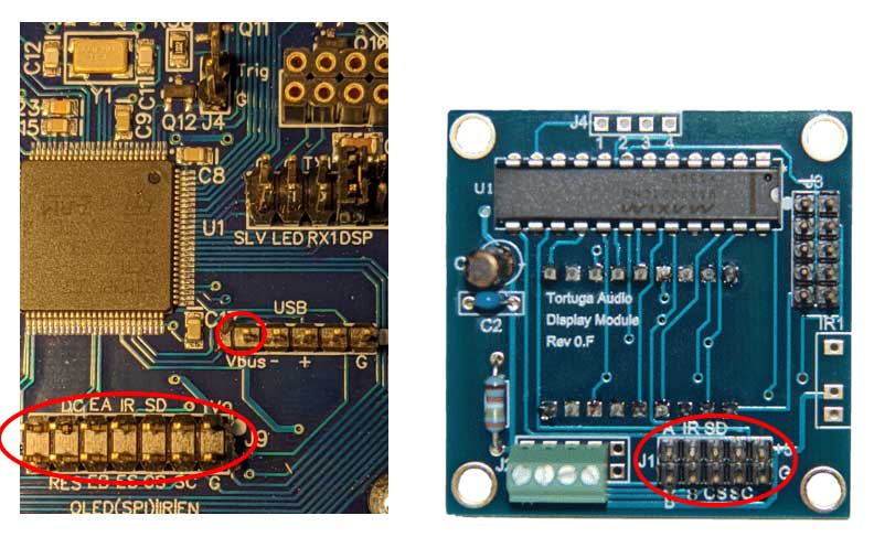
The connection from the V25 board to the DM1 7-segment display varies depending on the version of the V25 board. There are 3 versions of the V25 board – A, B & C. Both A & B use a single 10 pin ribbon cable from V25.J3 to DM1.J1. Version V25.C requires several individual female-female square pin jumper wires to connect from pins on V25 headers J8 and J9 to DM1 header J1.
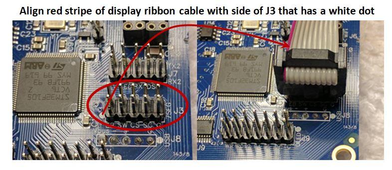
In the case of versions A & B please note that the red stripe on the ribbon cable must be aligned with the side of the J1 and J3 headers that has the white dot.
The table below shows the V25 to DM1 connections for each of the 3 versions of the V25 board. Some of the version C connections are not strictly required for the DM1 itself but are signals for the IR remote sensor and manual encoder that interface on or through the DM1.
| V25 Version | Signal | From V25 | To DM1 (master module) |
|---|---|---|---|
| Versions A & B | All | Ribbon cable from V25.J3 header… | DM1.J1 header (align red stripe with white dot at each end) |
| Version C | +5V power | V25.J8.Vbus | DM1.J1.+5 (square pin female-female jumper wire – typical for all) |
| Ground | V25.J9.G | DM1.J1.G | |
| SPI chip select | V25.J9.CS | DM1.J1.CS |
|
| SPI serial clock | V25.J9.SC | DM1.J1.SC | |
| SPI serial data | V25.J9.SD | DM1.J1.SD | |
| Infrared (for Apple IR remote) | V25.J9.IR | DM1.J1.IR | |
| Encoder switch (for encoder) | V25.J9.ES | DM1.J1.S | |
| Encoder leg A (for encoder) | V25.J9.EA | DM1.J1.A | |
| Encoder leg B (for encoder) | V25.J9.EB | DM1.J1.B |
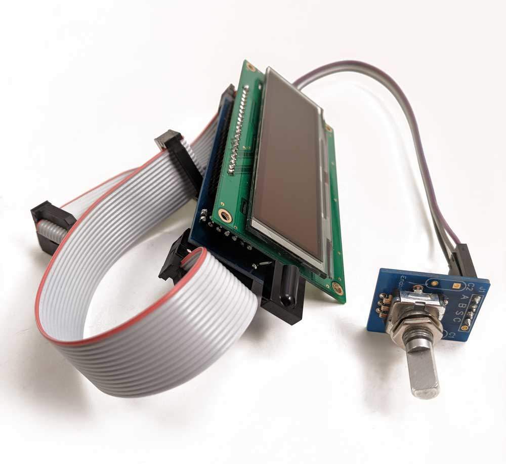
OLED display
The OLED Display Module (sold separately) is a highly interactive, easy to use, menu driven user control interface for configuring and controlling the V25.
The OLED display connects to the V25 via a 14 pin ribbon cable to the V25.J9 header.
Please refer to a separate document on the OLED display for more detail on its interface.
dfdfa
External control via UART | J7
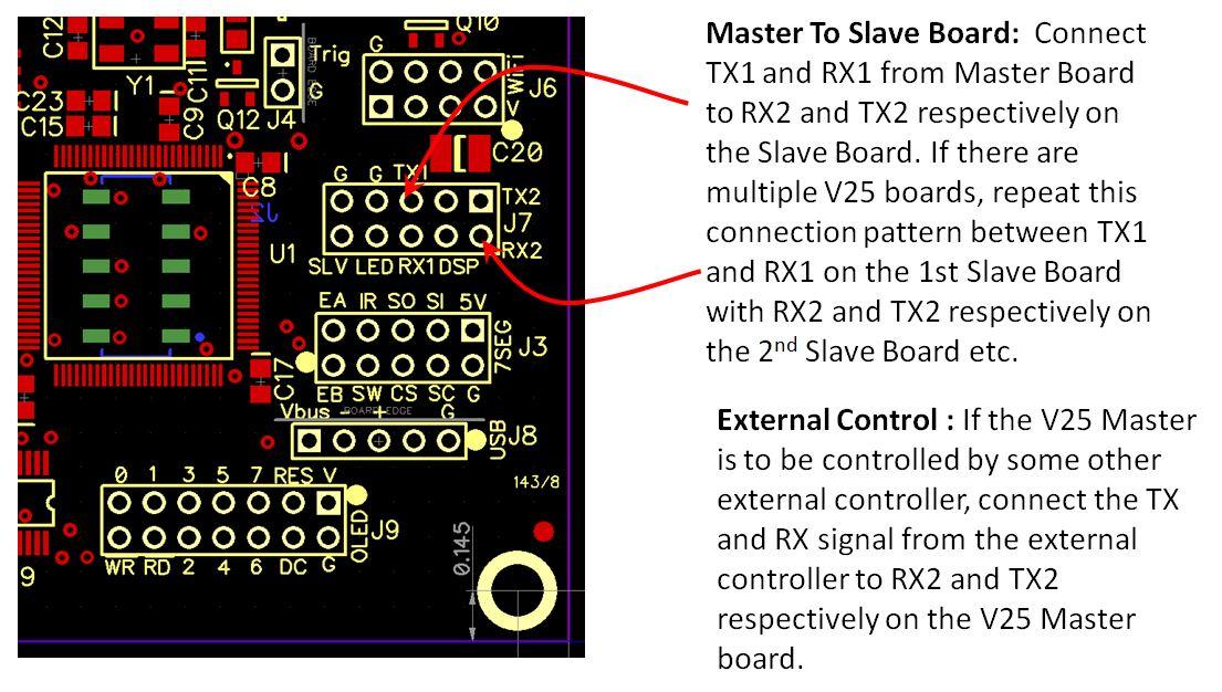
The V25 Preamp Controller Board can be controlled by interfacing it with any PC, microcontroller or programmable device that’s equipped with standard UART serial communications hardware or the equivalent in software. External UART TX and RX signals can connect to the V25 J7.RX2 and J7.TX2 pins respectively.
In order to have reliable UART communications the user should be mindful that both devices share a common ground.
UART Protocol
The UARTs used by the V25 are part of the V25’s microcontroller. They utilize data receipt interrupts, and are considered extremely accurate and reliable. The V25 employs the following UART communications configuration.
- Baud Rate: 115,200 bps
- Stop Bits: 1 stop bit
- Parity: none
- Data bits: 8
- Flow Control: none
UART control commands
The control commands available to an external controller are defined in the table below. Collectively these commands should allow for the comprehensive control of the V25 even in the absence of any visual feedback from the V25.
The user accepts all risks in using an external controller and commands to control their V25 controller. These commands are subject to change without notification.
| Command Value | Command Name | Desciption> |
|---|---|---|
| 0 | _power_toggle | toggles the on/off state of the controller |
| 1 | _turnon | turns controller on if it’s off otherwise ignores |
| 2 | _turnoff | turns controller off if its on otherwise ignores |
| 3 | _raise | response depends on controller mode – by default it raises volume 1 step |
| 4 | _lower | response depends on controller mode – by default it lowers volume 1 step |
| 5 | _left | response depends on controller mode – by default it shifts volume balance 1 step to the left |
| 6 | _right | response depends on controller mode – by default it shifts volume balance 1 step to the right |
| 7 | _enter | * volume adjust mode – blinks display * other modes – locks in any changes and reverts to default volume adjust mode |
| 8 | ** reserved ** | don’t use |
| 9 | ** reserved ** | don’t use |
| 10 | ** reserved ** | don’t use |
| 11 | _menu_vol | switches controller to default volume adjust mode |
| 12 | _menu_input | switches controller to input adjust mode |
| 13 | _menu_display | switches controller to display adjust mode |
| 14 | _menu_volmax | switches controller to max volume on input change adjust mode |
| 15 | _menu_imped | switches controller to impedance adjust mode |
| 16 | _menu_cal | switches controller to auto calibration mode |
| 17 | _mute_toggle | toggles mute state of controller |
| 18 | _mute | mutes the volume if not already muted |
| 19 | _mute_switch | mutes controller, then switches to new input (slow mode only), and then unmutes controller |
| 20 | _unmute | unmutes the volume if it’s currently muted |
| 21 | _refresh | refreshes display based on current mode |
| 22 | _show | display info associated with current mode |
| 23 | ** reserved ** | don’t use |
| 24 | ** reserved ** | don’t use |
| 25 | ** reserved ** | don’t use) |
| 26 | ** reserved ** | don’t use |
| 27 | ** reserved ** | don’t use |
| 28 | ** reserved ** | don’t use |
| 29 | ** reserved ** | don’t use |
| 30 | ** reserved ** | don’t use |
| 31 | _send_vol | * 2 bytes : command + value * value = volume level 0-99 |
| 32 | _send_volbias | * 2 bytes : command + value * value = volume bias between -20 and+20 |
| 33 | _send_volmax | * 2 bytes : command + value * value = max volume upon input change between 1 and 99 (99 essentially defeats this safely feature) |
| 34 | _send_input | * 2 bytes : command + value * value = input number between 1 and 6 |
| 35 | _send_imped_index | * 2 bytes : command + value * value = impedance index number between 1 and 5 |
| 36 | _send_imped_level | * 2 bytes : command + value * value = impedance level between 1 and 99 (must run autocal after changing level before change becomes active) |
| 37 | ** reserved ** | don’t use |
adfa
