About this manual
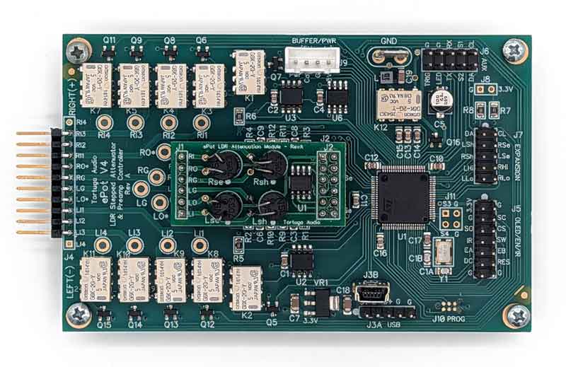
This manual provides information regarding the operation and control of the ePot V4 LDR attenuator & preamp controller board, generally referred as the V4.
This manual is being frequently edited and updated and is subject to change without notice.
The V4 has a separate hardware manual which describes its design basis, hardware features, and power/control interfaces. The V4 hardware manual can be found here.
The remote
The ePot V4 is designed to work with any infrared remote that is functionally similar to the original silver metal 7-button Apple remote which uses the NEC IR protocol.
Apple remote
Apple discontinued production of its original silver anodized aluminum remote in 2023. Used Apple remotes can still be found online from third parties sellers but tend to be unreliable or only partially functional. We recommend the alternative Function or Nettech remotes which are reasonably priced, and are widely available new online from Tortuga Audio, Amazon, and others.
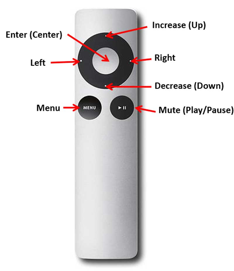
The Apple remote must first be paired with your Tortuga preamp controller. See the section on “Remote Pairing” under The V4 Controls below.
Nettech remote
Nettech makes a low-cost 7-button Apple remote clone that functions the same as the original Apple remote. The Nettech is easier for most people to hold in their hand compared to the smaller and thinner Apple remote. The Nettech is a cheap remote that gets the job done but has a cheap plastic feel and has somewhat squishy buttons.
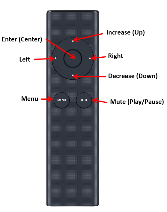
You can purchase a Nettech remote directly from Nettech via this link.
Like the Apple remote, the Nettech remote must first be paired with your Tortuga preamp controller. See the section on “Remote Pairing” under The V4 Controls below.
Function remote
The Function remote is a higher quality Apple remote alternative. This remote also serves as an alternative remote for a wide range of TVs and other audio-visual equipment.
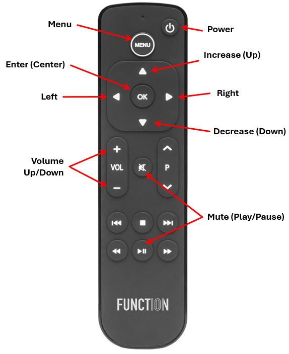
This remote has a good feel in your hand and the top surface has a satisfying rubberized surface with nicely responsive buttons. The downside of the Function remote is that it’s a more complex device and may create conflicts with other equipment but there are usually workarounds for these conflicts. Tortuga Audio recommends the Function remote.
Some aspects of the Function remote will work without first pairing it with your preamp controller, however, it must be paired to be fully functional. See the section on “Remote Pairing” under The V4 Controls below.
The OLED display
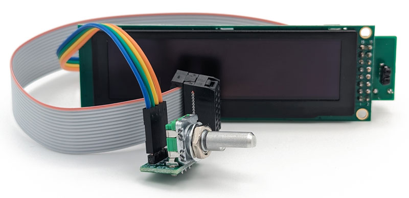
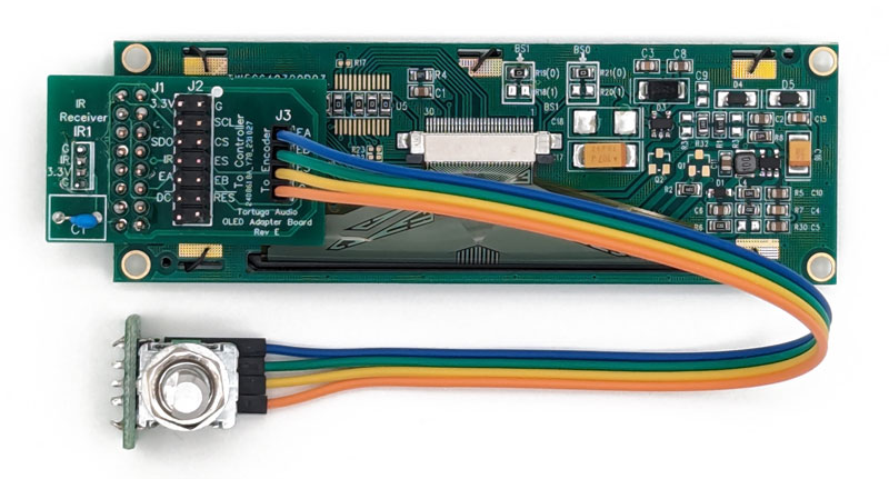
The OLED display is a 3.2 inch, 256×64 bit, high contrast, white-on-black graphical display. It works interactively with the remote to allow the user to navigate a control menu tree to adjust controls or change options. The OLED display is capable of displaying a wide range of text, numbers, lines, and images with each pixel having a 4 bit grayscale brightness level between 0 and 15. The high contrast display enables the user to easily view, configure and control the V4 based preamp.

The V4 Controls
The V4 is a visually oriented menu driven preamp controller that uses an OLED display together with an infrared remote and rotary encoder with an integral push button. The V4 is fully controllable using the remote, and only partially controllable with the encoder.
The V4 control menu structure is outlined below. Each control is explained in the expandable accordion section that follow. Sections that include “(menu)” in their label refer to specific controls in the menu structure. Sections without “(menu)” in their label discuss other control actions.
| Menu label | Control action(s) | Additional control action |
|---|---|---|
| Volume | Adjust volume level (default) * Adjust channel balance (optional) * Switch input (optional) | |
| Input | Switch between inputs | Edit input labels |
| Balance | Adjust channel balance | |
| Display | *Adjust brightness *Set display timeout (optional) | |
| Imped/Cal | *Adjust impedance setting/level *Initiate calibration | Calibration status/control |
| #Inputs | Adjust max # of inputs | |
| VolRamp | Adjust volume ramping options * Ramp up only * Ramp down only * Ramp both up and down * No ramping | |
| VolControl | Volume control options | |
| VolUnits | Volume display options | |
| VolMax | Max volume option | |
| Version | Hardware/firmware information | |
| System | Set system type * Single-ended (default) * Balanced | |
| Firmware | Put system into firmware update mode | |
| Reset | Reset/clear all calibration data | |
If you are new to the Tortuga V4 preamp controller, we recommend you first review the “About the control menu” section. It explains the conventions and rules before getting into specific controls.
Overview
The V4 uses a menu driven control scheme with tight integration between the remote and the OLED display. A limited number of control actions are also possible using only the rotary encoder which has a built-in push button feature.
The control rules
The following “rules” govern the operation of the control menu.
Menu labels
Each control has a menu label identifying its function. These menu labels are listed in the menu structure table below under the “Menu Label” column.
Navigating the menu
The menu is a linked list of vertical labels that the user navigates up and down using the up (raise) and down (lower) buttons on the remote. You can not navigate the control menu using the encoder. The control menu list is shown in the “Menu label” column in the menu structure table below.
You access the menu by pressing the “Menu” button on the remote.
Selecting a menu item
The menu item currently displayed is selected/activated by pressing the center button on the remote. For example, if the “Balance” menu item is currently being displayed, pressing the enter button will activate the balance control action/view.
Control action
When you select a menu item, you leave the menu items list and activate the selected control action. Within each control action, you use the buttons on the remote control (raise, lower, left, right, menu, mute and center) to manipulate the controls specific to each control action. This is difficult to explain in text form and relatively easy and intuitive to understand with a little hands-on experience.
For example, when you are in the default volume control action view, the raise/lower buttons on the remote raise and lower and volume level.
Volume control | the default control action
The volume control action is the default control action. This is where you’ll spend 99% of your time. You can usually return to the default volume control action/view by simply pressing the center button or menu button on the remote one or more times – kind of a universal “escape to home”.
Escape via Menu button
Pressing the Menu button on the remote will exit the current control action/view and revert back to the associated menu item. Pressing the Menu button again will revert you back to the default volume control action view.
Escape via Center button
Pressing the center button on the remote will usually exit the current control action/view and revert directly back to volume control action/view.
When power is applied to the V4 (as distinct from turning the V4 on or off), the controller goes through a brief boot-up process. During the brief boot process, the message “Boot” will be briefly displayed and then be replaced with the image of a turtle (the “Tortuga”) which then fades to black. The V4 is now booted up, turned off and is in standby mode ready to be turned on and operated normally.
Overview
When the OLED display is blank/off, the V4 may indeed be turned off and in standby and will turn on in response to any control input from either the remote or the encoder.
A blank/off display may also be because the controller is disconnected from a power source in which case the controller will not respond to any control input.
Lastly, a blank/off display may also exist because the display has timed out and has temporarily turned itself off but the controller remains turned on and fully operational. Any control input from the remote or encoder will immediately “wake up” the display. See the section on “Display options” for more information on the optional display timeout feature.
Information (turn on sequence)
When the V4 turns on it will splash the “Tortuga Audio” name on the display followed soon after by the model name (typically “ePot V4 Max”). The Tortuga Audio name will then fade away and the controller will be in its default volume control mode. During turn-on, the volume will either smoothly ramp up to, or go immediately to, its prior volume set point depending on the volume ramping settings discussed in section “Volume Ramping”. Also, see section “Volume” for more details on how volume controls work.
Controls
When turned off and in standby, the V4 controller will turn on in response to any control input from either the remote or the encoder.
Overview
The controller can be turned off using either the remote or the encoder.
When the controller turns off, the display will briefly show an “Off” message followed by the Tortuga image which then slowly fades to black. Once the display is clear, the controller is now off and in standby mode.
Turning off via remote
There are two ways to turn off the controller using the remote.
Dedicated power button
The Function remote has a dedicated power toggle button in the upper right-hand corner that can be used any time to turn the controller on or off.
Mute sequence
The controller can be turned off by first muting the volume and then pressing the enter (center) button. During muting, the volume will ramp down to zero and the display will then show the “Mute” status label. Subsequently pressing the enter (center) button on the remote will turn off the controller.
Turning off via encoder
Press/hold-in the push button on the encoder for greater than 2 seconds but less than 10 seconds while also avoiding turning the encoder and then release. This will initiate the turn-off sequence.
Overview
Selecting the volume menu will take you to the volume control. Volume control is the default control view. Wherever you are in the menu tree, pressing the Menu or Center button will eventually return you to the default volume control view where you will spend 99+% of your time.


Information
Numerical volume level
Numerical volume level is displayed by default as a volume step between 1 and 100. The user may elect to have the volume shown in units of decibels (dB) ranging from -60 to 0 dB in increments of ~0.6 dB per step (no example provided here). See section on “Vol Units” for changing the displayed units.
Please note that reducing volume below step 1 will fully mute the volume and the numerical volume level will read as “Mute”.
Volume bar
A horizontal volume bar is displayed below the numerical volume level. The volume bar provides a visual indication of volume between 0 and 100%.
Input
The upper left corner shows the current selected input # followed an input label. The example shown above indicates input #1 is currently selected and has the default label of “Input1” which can be edited by user. See section on “Inputs” for editing the input labels.
Controls
Volume adjustment
When volume control is active, pressing the raise or lower button on the remote, or turning the encoder right or left, will increase or decrease the volume level. Holding down either the raise or lower button on the remote will cause the command to repeat automatically.
Muting
When the volume control is active, pressing the Mute/Play button on the remote will cause the volume to ramp down and fully mute. You can achieve the same by a brief press/release on the encoder push button. Repeating this control action will toggle the volume mute status.
When the unit is already muted, hitting the mute control again will un-mute the unit and the volume will ramp up to the previous volume set point.
The muting behavior can be altered via the “Vol Mute” menu feature described in a separate section below which allows the user to select how the volume ramps down when muted and ramps back up again when un-muted.
Balance adjustment
When volume control is active AND volume control is in balance adjustment mode (see “Vol Controls” menu for details), the left and right buttons on the remote will move the channel balance 1 step in the given direction. You can achieve the same with the encoder by press/holding-in the encoder push button while simultaneously turning the encoder left or right.
Input switching
When volume control is active AND volume control is in input switching mode (see “Vol Controls” menu for details), the left and right button on the remote will switch the input in the given direction. You can achieve the same with the encoder by press/holding-in the encoder push button while simultaneously turning the encoder left or right.
Overview
Selecting the input menu will take you to the input control. Input control lets you switch between connected inputs. Please note that you can also switch between inputs using the default volume control provided you have also set the “Vol Controls” option to switching inputs.


Information
Input number & volume
The current input number and associated volume level are shown in the upper left corner of the input control display. For example, “#3|59” indicates input #3 is currently set at volume step 59.
When you switch inputs, the volume associated with the current input is saved, and the volume last associated with newly selected input becomes the new volume setpoint. The saved volume is limited to a maximum initial value that is set by the “Vol Max” option.
Note that you can edit the maximum initial volume level when the preamp is turned on or when switching between inputs. It’s set at step 60 by default. See section on “Vol Max” for details on editing this value.
Input label
The current input label is prominently shown in the center of the display. The inputs are labeled by default as Input1, Input3 etc. The labels can be edited and have up to 10 characters in length.
Controls
Input switching with remote
When the input control is active, pressing the right or left buttons on the remote, will switch to the next input. If already at input #4 (the highest input), pressing the right button on the remote will switch back to input #1. Similarly, if already at input #1, pressing the left button on the remote will switch back to input #4.
Holding the right or left button down on the remote will automatically cause the input to continue the sequence of switching to the next input.
Input switching with encoder
Input switching can be done at anytime using the encoder by pressing in the push button on the encoder and then simultaneously turning the encoder right or left.
Input switching sequence
Regardless of whether initiated via the remote or the encoder, input switching occurs per the following sequence:
- The label “Switching” will be displayed replacing the current input label
- If volume ramp down is enabled (see “Vol Ramping”), the volume will ramp down to zero, otherwise it will go to zero immediately
- Once volume has ramped down to zero, the current input relay will be disconnected and the muting relay will short the audio output
- The “Switching” label on the display will be replaced by the label of the newly selected input
- Next the newly selected input relay is connected
- Finally, the audio output relay un-mutes the shorted output, and if volume ramp up is enabled, the volume ramps up to the stored volume level last associated with the newly selected input. If volume ramp up is disabled, the volume goes to this volume level immediately.
Alternative method using volume control view
Input switching can also be done via the remote (only) while in the default volume control view provided the volume control option is set to input switching instead of channel balance. See section “Volume control options” for more information on this option and also the section “Adjust volume level”.
Input label editing (remote only)
When the input control is active, pressing the Mute/Play button on the remote places the input control into input label editing mode. Input label editing allows the user to edit the label associated with the current selected input. The input label can be up to a maximum of 10 characters in length. The default input labels are typically “Input1”, “Input2” etc.
Character highlighting – The currently active character (selected for editing) in the label is visibly brighter than its neighbors. You move between active characters using the left and right buttons on the remote.
Adding new characters to label – When you use the right button on the remote to move beyond the right-most character in the label, a new character “a” will be added to the label.
Deleting a label character – To delete the currently highlighted character, press the Mute (Play/Pause) button on the remote.
Edit a label character – Use the raise/lower buttons on the remote to edit the currently highlighted label character. Allowable characters include letters A-Z, a-z, and numbers 0-9. You can easily scroll through these letters and numbers using raise/lower buttons.
Overview
The channel balance feature allows the user to adjust the channel center balance to the left or right as desired. Each adjustment step represents approximately 0.6 dB of bias in the given direction. You can bias the controller up to a maximum 20 steps (12 dB) left or right. The channel balance adjustment algorithm attempts to maintain the same overall volume level as bias is added to one side or the other.


Information
The channel balance control view shows the number of channel balance bias steps in either the Left or Right direction. There are a maximum of 20 bias steps. When the channel balance is neutral, no Left or Right bias values are shown. The display will blink briefly each time the channel balance is returns to the neutral position.
Controls
Channel balance can be adjusted left or right using both the remote and the encoder.
Balance adjustment via remote
While in the channel balance control is active, use the left and right buttons on the remote to adjust channel balance left or right. Each click on the remote moves the channel balance 1 step which is equivalent to 0.6 dB change.
Balance adjustment via encoder
While in the channel balance control is active, press/hold-in the encoder push button and then turn the encoder clockwise for right channel bias and counterclockwise for left channel bias.
Alternative method using volume control view
Channel balance can also be adjusted via the remote (only) while in the default volume control view provided the volume control option is set to channel balance instead of input switching. See section “Volume control options” for more information on this option and also the section “Adjust volume level”.
Overview
The Display control allows the user to adjust the display brightness and to optionally enable and adjust a display timeout feature. Brightness is adjustable between 1-14 with 14 being the brightest. The display timeout can be adjusted between 5 and 99 seconds. Reducing the timeout to less than 5 seconds simply turns off the display timeout feature.
When the display timeout feature times out, it turns off the display. Any control input from either the remote or the encoder will immediately “wake up” the display if it’s already turned off and will always restart the timer regardless of whether the timer has timed out yet or not.


Information
Brightness level
The left side of the display control view has the label “Brightness” under which you’ll find a value between 1 and 14 indicating the current brightness setting.
Timeout seconds
To the right of the “Brightness” label you’ll find the “Timeout” label under which you’ll find the “Off” text when the timeout feature is disabled. When the timeout feature is enabled, the “Off” is replaced by a timeout value between 5 and 99 seconds.
Controls
Display brightness and timeout settings can only be adjusted using the remote.
Adjusting display brightness
Use the raise/lower buttons on the remote to increase/decrease the display brightness between 1 and 14.
Adjusting display timeout
By default, the display timeout is disabled unless explicitly enabled by the user. When disabled, the timeout value will say “Off”. Use the right button on the remote to enable the display timeout feature by setting the timeout value between 5 and 99 seconds. Use the left button to reduce the timeout value. Going below 5 seconds will turn off the timeout feature.
Overview
Adjustable impedance and built-in LDR calibration are interrelated features of Tortuga Audio’s LDR attenuators and preamp controllers. They are also both unusual and unique within the stereo audio community. Therefore, we encourage users that are new to Tortuga Audio’s LDR technology to explore our online documentation section on adjustable impedance and LDR calibration which can be found here.
The Impedance/Calibration control allow the user to adjust the input impedance of the V4 and to initiate calibration of the LDRs at the currently selected impedance setting number and level.
The V4 is configured by default to operate at impedance setting #1 with the input impedance level fixed at 50k ohms. This default setting and level can not be changed, however, the user may optionally configure up 9 additional impedance settings with each setting adjusted to an impedance level ranging from 1k to 99k ohms. Once one or more additional settings is configured and calibrated, the user may switch between impedance settings/levels while listening to music. In this manner, it’s possible to determine if there is an optimal impedance setting for your equipment setup.
Note that configuring and using additional input impedance settings is entirely optional, is provided solely for the curious user, and can be entirely ignored.
Information
Menu
Impedance and calibration occupy a single “Imped/Cal” menu item because the topics are so closely related.

Default setting #1 | 50k
By default, impedance setting #1 is pre-configured by Tortuga Audio and set to a fixed impedance of 50k ohms. This #1 setting cannot be deleted or edited, but the user may run calibration at setting #1 at any time.
Optional settings #2-10
User may opt to configure additional impedance settings each with its own impedance level between 1k and 99k. There are 9 additional impedance setting slots set aside for this purpose. Examples of setting #2 control views are shown above.
Calibration status | OK
An OK calibration status indicates that the setting/level has successfully been calibrated and that the controller should be fully operational at the current impedance setting and level.

Calibration status | Off
Optional setting #2 through #10 are all set to the “Off” status by default. The optional settings remain inactive (“Off”) until such time as their impedance values are manually adjusted to a desired impedance level.

Calibration status | Locked
There are numerous rules governing the “LOCKED” calibration state which are important to understand.

When an impedance setting/level is marked “Locked”, it means:
- The setting/level combination has not been through calibration or even if it had been previously it now requires calibration be performed again
- You will not be able to switch to another setting including even the default setting #1. A “Locked” setting demands resolution before moving on.
- A rectangular outline will slowly blink until such time as the condition is resolved
- The audio output will remain muted (no audible output) until such time as the condition is resolved
- There are only 2 ways to resolve a “Locked” impedance/calibration setting.
- #1 Successfully run a calibration cycle at this setting/level, or;
- #2 Manually reduce the impedance level back to zero which effectively turns that setting “Off” again and allows you to switch to another setting
Locked – The Blinking Frame
When the calibration status is locked for any reason, a slowly blinking rectangle will frame the OLED display until such time as the current impedance setting is either disabled or successfully run through a cycle of calibration.
Calibration status | Locked – The Blinking Frame
Calibration status | Running
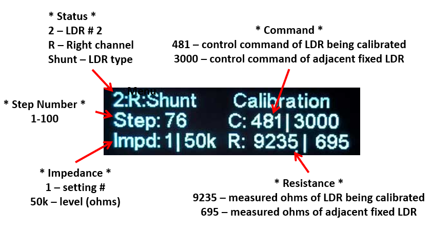
Once calibration is started, the calibration status display will show the information described below. This information is mostly relevant as a diagnostic tool and can usually be ignored. A complete calibration cycle usually takes no more than 15 minutes. The process will slow down and speed up which is normal.
Status: Shows the LDR number (1-4) followed by channel side (right or left) and finally the LDR type (series or shunt).
Step Number: Shows the calibration step number of the current LDR. The step starts at 1 and ends at step 100 and then repeats for the next LDR. There are 4 LDRs for single-ended systems and 8 for balanced systems so a full calibration cycle will go through 400 total steps for a single-ended system and 800 steps for a balanced system.
Impedance: Shows the impedance setting number (1-10) and the impedance level in units of 1000 ohms associated with the impedance setting number. Default setting #1 is fixed at 50k ohms. The user may opt to enable and configure up to 9 additional impedance settings each with its own impedance level.
Command: The “C” line shows 2 values. The left value is the current 16 bit command value generated by the microcontroller as it attempts to reach the targeted LDR resistance value associated with the current calibration step and impedance level. This value will likely be changing rapidly. The right value is a fixed command value for the adjacent LDR which is held at a fixed resistance while its mate is being calibrated.
Resistance: The “R” line shows 2 values. The left value is the measured resistance of the LDR currently being calibrated with the current command value. This value will likely be changing rapidly which is normal. The right value is the resistance value for the adjacent LDR which is held at a fixed command while its mate is being calibrated. The right value will change only slightly which is normal.
Controls
Adjust impedance setting #
Use the raise/lower buttons on the remote to switch between impedance settings 1 through 10.
Adjust impedance level
Use the left/right buttons on the remote to decrease/increase the impedance level of the current setting between 1k and 99k ohms.
Note that the impedance level for setting #1 is fixed at 50k and cannot be adjusted.
Start calibration cycle
While in the Imped/Cal control view, press the Mute(Play/Pause) button on the remote to commence a calibration cycle for the current impedance setting/level. Note that there may a few seconds delay before the display begins to show the calibration running status as described above.
Once started, the calibration process will attempt to calibrate the 4 (single-ended system) or 8 (balanced system) LDRs by sequentially running each LDR through 100 calibration steps. The entire process usually takes 15 minutes or less.
When the calibration process has completed the last LDR, the controller will automatically revert back to the default volume control view and resume normal operation.
Skipping LDRs during calibration cycle
At any time during an active calibration cycle, the user may opt to skip forward and backwards between LDRs by using the right/left buttons on the remote. This will interrupt the calibration of the current LDR and start calibration of the next or previous LDR starting at step 1. Skipping LDRs is normally not advised or required but is available as a diagnostic tool.
Stopping the calibration cycle
The user may stop and cancel the calibration cycle at any time by pressing the Menu or the Enter(center) button on the remote. Pressing the Menu button will revert back to the Imped/Cal control view. Pressing the Enter button will revert back to the default volume control view.
Stopping the calibration cycle prematurely will not damage the LDRs or the controller in any way, however, it may result in sub-optimal calibration results and is generally not recommended practice.
Overview
The user has the option to adjust the total number of possible inputs that the V4 can switch between. The V4 can switch between up to 4 different inputs. By reducing the default from 4 inputs down to say 2, only inputs #1 and #2 will switch on when selected.
This value is set at the maximum possible of 4 by default. Most users will never change this control option. But if you only have one or two devices connected to your preamp, this option can avoid future confusion when switching between multiple input sources.


Information
The control view shows the number of inputs currently able to be switched between up to a maximum of 4. This value can be adjusted between 1 and 4.
Controls
The number of possible inputs can be manually adjusted using the raise/lower buttons on the remote.
Overview
The V4 controller offers the option of having the volume level smoothly ramp up and/or ramp down during muting or transitioning between inputs. The alternative to ramping the volume is having the volume transition immediately from muted to full setpoint level and visa versa. The controller is set by default to ramp up the volume only.


Information
The volume ramping control view shows the currently selected option. The 4 volume ramping options are described below.
Option #1 – No ramp down | Ramps back up (default)
Volume will mute immediately. When un-muting, the volume will smoothly ramp back up to its previous setpoint.
Option #2 – Ramps down | No ramping back up
Volume ramps down smoothly when muting or changing input. Volume returns immediately back to previous setpoint.
Option #3 – Ramps both down and up
Volume ramps smoothly both down and up when muting, un-muting or changing input
Option #4 – Ramping disabled
Volume ramping is disabled. Volume goes immediately to zero and back up to previous setpoint when muting, un-muting or changing input.
Controls
Use the raise/lower buttons on the remote to cycle between the 4 control options cited above.
Overview
The default volume control/view discussed under “Adjust volume level (menu)” has secondary controls that allow the user to either switch between inputs or adjust the channel balance, all without leaving the volume control view. The “VolControl” options allows the user to choose between these secondary controls.


Information
There are only two options available each of which are described below.
Option #1 – Adjust balance (default)
Selecting this option means that while in the volume control view, the right/left buttons on the remote will adjust the channel balance.
Option #2 – Switch input
Selecting this option means that while in the volume control view, the right/left buttons on the remote will switch between inputs.
Controls
Use the raise/lower buttons on the remote to switch between the 2 control options cited above.
Overview
The VolUnits control allows the user to select between having volume shown as a step number (default) or in units of dB (decibels) of attenuation.


Information
Option 1 – Step number (default)
Volume is displayed by default as a volume step number between 1 and 100.
Option 2 – decibels (dB)
Volume is displayed in units of decibels (dB) ranging from -60 (minimum volume = maximum attenuation) to 0 (maximum volume = minimum attenuation)
Controls
Use the raise/lower buttons on the remote to switch between the 2 control options cited above.
Overview
The VolMax control is an equipment protection feature that allows the user to adjust the maximum allowable initial volume when the preamp gets turned on or when inputs are switched.
For example, let’s say the preamp had been set on input #2 when last turned on and the volume had been on step 80 when the preamp was turned off. Let’s also assume that the Vol Max setting is set at 60 (default). When the preamp is next turned on, the preamp will first recover the saved volume setting of 80 associated with input #2 but will reset it to 60 before the actual preamp volume level command is transmitted to the attenuation circuit.
VolMax is set at step 60 by default but is adjustable by the user and can be set anywhere from 1 to 100. Setting VolMax value at 100 fully defeats the purpose of this feature which is to save your equipment (speakers mostly) from damage from accidentally playing music too loud.


Controls
Use the raise/lower buttons on the remote to increase and decrease the VolMax setting.
Overview
Selecting this menu item provides information only. There is no control action associated with this menu item, only information about the hardware and firmware.


Information
The following information is available from the control view.
Model name
The first line of information is the product name. In the example above, the model is the “ePot V4 max”
Hardware version
The first part of the second line indicates the underlying hardware version of the V4 controller. In the example above (“HW:Rev-A”), the hardware version is Rev-A.
Firmware version
The second part of second line indicates the current firmware (software) version running on the hardware. In the example above (“FW: 100”), the firmware version is 1.0.0.
System type
The final part of the second line indicates the system type which can be either single-ended (“sEnd”) or balanced (“Bal”). In the above example, the system type is sEnd.
Serial Number
The third and last line of information is the serial number of the V4 controller board.
Controls
There are no controls associated with this item.
Overview
This control allows the user to place the V4 controller into firmware update mode. This control starts a factory provided utility program within the V4’s microcontroller called the “bootloader”. Once the controller is in firmware update mode, the V4 will longer respond to any further user control inputs from the remote or encoder.
While in firmware update mode, the V4 controller waits to connect with the STM32CubeProgrammer which is a PC/Mac software application used to upload new firmware into the V4 board. The STM32CubeProgrammer communicates with the V4 board through its USB interface.


Information
Detailed instructions on how to update the V4’s firmware is provided in a separate document that can be found **TBD**.
No information is provided in the control view aside from the instruction to press the center/enter button on the remote 5 times to start the V4’s internal bootloader which puts the V4 controller into firmware update mode.
Controls
While in the control view, press the center/enter button on the remote 5 times to put the V4 controller into firmware update mode. A numerical counter will keep track of the button press count. Upon the 5th press, the V4 will enter firmware update mode after which the V4 controller will no longer respond to control inputs.
Overview
Reset allows the user to erase all impedance and calibration data. This should be rarely necessary but is provided as convenient method for clearing out previous data.
Note that after running Reset, you MUST run calibration (recommend twice) to rebuild the attenuation tables for the default #1 impedance setting.


Controls
Start reset process
To start the reset process, press the right button on the remote 5 times in a row. A button press counter shows the count. Upon the 5th press, the reset process will reset the calibration data for each of the 10 impedance settings.
Note that after the reset process is completed, the controller will revert back to the default volume control view. At that point the V4 has no calibration data and therefore calibration must be run for the default impedance setting/level #1/50k.
Until such time as calibration is completed again for the default impedance setting/level, the V4 controller will not generate any audible output.
Overview
The OLED display will enter screensaver mode after 15 minutes of control inactivity by the user. Any control input from the remote or encoder will cause the controller to immediately exit screensaver mode and reset the screensaver timer. While in screensaver mode, the display will show a small turtle (the Tortuga) that will move about the display every few seconds. The purpose of the screensaver is to avoid “burn-in” of the OLED display which can happen if a static image persists over long periods of time.
There are no controls associated with the screensaver feature. The screensaver feature can’t be disabled and the 15 minute timer can’t be adjusted.
Overview
Remotes, such as the Apple remote and many of its clones, will only be fully functional if they are first “paired” with the item of equipment they are supposed to control. These remotes send a unique ID number as part of each infrared command. In the case of the Apple remote, there are 256 possible unique ID numbers between 0 and 255. “Pairing” is the process of teaching the equipment item the ID number of a remote such that it only responds to that remote and no other.
The Apple remote ID numbering scheme allows you to own multiple products each responding to a different Apple remote in order to avoid conflicts. For this to work each product must be deliberately paired with a remote with a unique ID number.
Pairing procedure
The pairing procedure for the V4 series controller is as follows:
- First, turn on the preamp/controller
- Press/hold-in the encoder push button for 10+ seconds during which time the display will seconds counting up. Do not rotate the encoder while the push button is pressed.
- When the pairing counter reaches 10 seconds, the display will changes and indicates the unit is in pairing mode. You can now release the encoder push button.
- Then press the Center button on the remote. This should complete the pairing process and the preamp should revert to the default volume control action view.
- Repeat the above procedure if the controller still does not respond to the remote

