The Evolution of LDR Volume Control

LDR Volume Control
There’s growing recognition within the community of audio enthusiasts (a.k.a. audiophiles) that LDRs (light dependent resistors) deliver the best sounding volume control technology available today. Over the past 5 years, Tortuga Audio has been leading the charge to evolve and perfect LDR based volume control.
In Q2 2017 Tortuga Audio released its fourth generation LDR technology which is included in all of our current passive preamp products.
Tortuga Audio’s LDR technology moves beyond the old challenges of integrating LDRs into audio volume control. For those who like to look under the hood, here is a brief review of the evolution of LDR volume control.
How LDR Volume Control Works
To understand LDR volume control let’s first review volume control with a conventional potentiometer or “pot”.
Potentiometers used for volume control will have a fixed resistance rating that is typically between 10k and 100k ohms. The audio input signal connects at one end of this fixed resistance and the other end is connected to ground. The output signal from the pot is a third connection to what’s referred to as the “wiper” which slides along the pot’s fixed resistor. The output signal of the pot comes from the wiper.
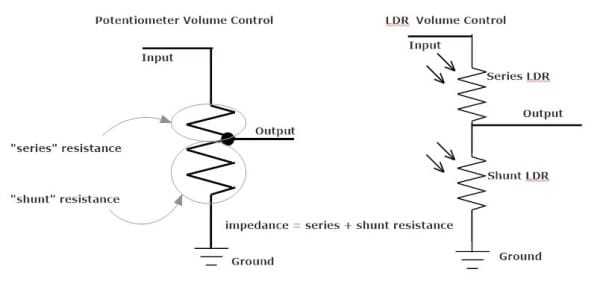
The resistance above the wiper is the series resistance (Rseries) and the resistance below the wiper is the shunt resistance (Rshunt). The resistance Ratio is defined by the formula: Ratio = Rshunt/(Rshunt + Rseries). This Ratio also happens to be the voltage ratio of Vout divided by Vin such that Vout = Vin x Ratio. Putting all this math together the resulting attenuation expressed in decibels is defined as: dB = 20 x log(Ratio) or if you like dB = 20 x log (Vout/Vin) where Ratio = Vout/Vin = Rshunt/(Rseries + Rshunt).
Thus, when Rseries is zero the volume is maximum (no attenuation) and when Rshunt is zero the volume is minimum (maximum attenuation).
Volume control with an LDR is conceptually similar to a potentiometer.
With LDRs, attenuation is achieved by varying the resistance levels of 2 separate series and shunt LDRs to achieve specific resistance ratios that correspond to specific dB attenuation levels. With a pot all this is done mechanically whereas with LDRs it’s done electronically and thus can be manipulated in ways that you can’t with a pot.
First Generation – Matched LDRs
First generation LDR volume control was entirely dependent on sorting through literally 100’s of LDRs and finding 4 (2 series and 2 shunt) that had the same resistance characteristics. Matching was key to achieving proper left/right channel balance. Done right, matching LDRs was a labor intensive process that required a fair bit of testing and data processing; a considerable investment in both time and money.
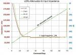
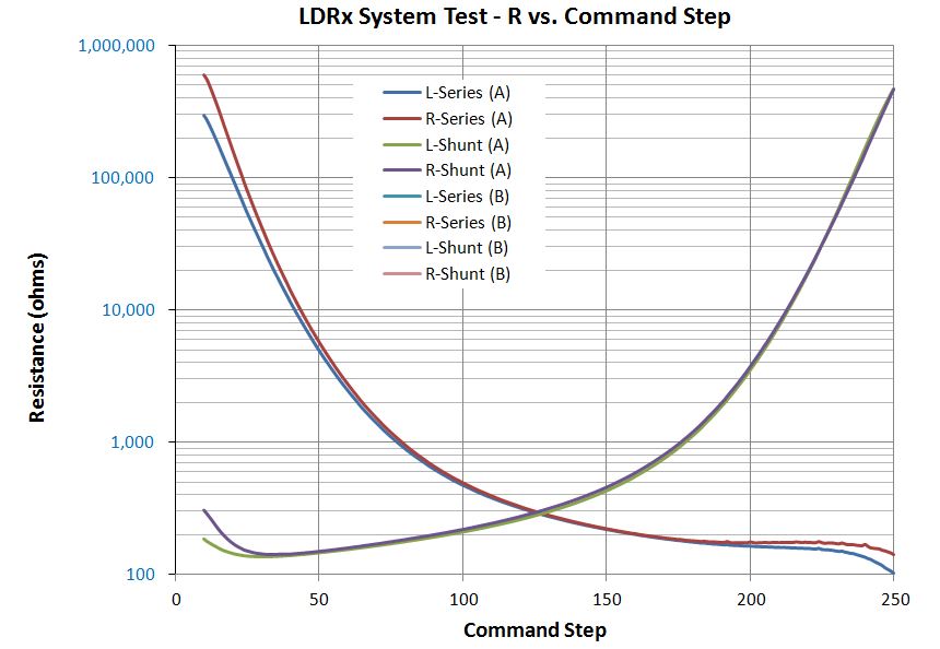
The graph below shows the results of 4 well matched LDRs being tested for compliance over a nominal 100 to 100,000 ohm range; 2 are series LDRs and 2 are shunt. Here the control voltage has been divided into 250 discrete and equal steps.
One key drawback to this approach is that the input impedance (combined series & shunt resistance) not only varies across the control range but drops down to just a few hundred ohms around mid-range. Extreme low input impedance will reduce the dynamic punch and bottom end of the audio signal. This can be partially mitigated by using amplifiers that have very high input impedance relative to your source’s output impedance (100:1 or higher) but this is far from ideal.
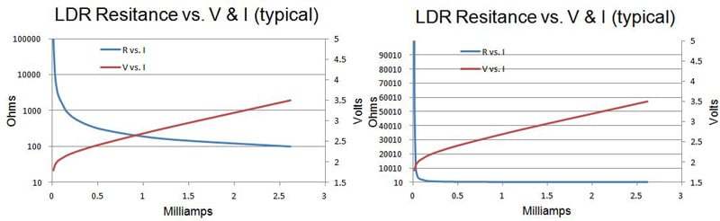
Matching LDRs isn’t a trivial matter because LDR’s are higly nonlinear. The charts below highlight the nonlinear relationship between LDR resistance and control voltage/current for a typical LDR. The chart on the left shows the resistance using a logarithmic scale so the nonlinearity is obvious but muted. The second chart on the right (same data!) shows this relationship using a linear scale. Nonlinear indeed!
The implication here is that precise control of LDR resistance (and thus volume) cannot be achieved by a simple linear “one size fits all” approach to regulating their control voltage.
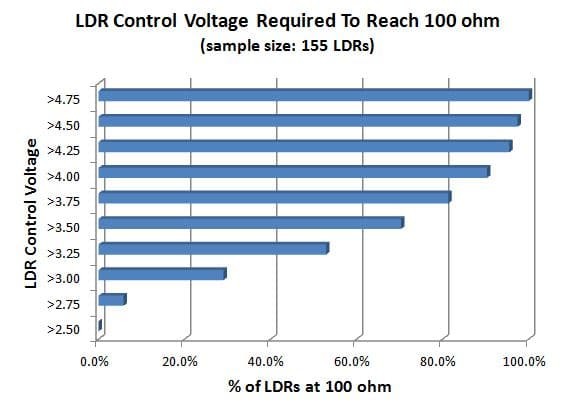
In addition to being nonlinear, LDRs are also highly variable which makes matching them all the more challenging. Tortuga Audio operates its LDRs between approximately ~100 and ~100,000 ohms. Thus in order to have 4 matched LDRs, we would ideally like these 4 LDRs to reach these resistance levels with the same control voltage.
The chart below shows the voltage level needed to reach 100 ohms in a random collection of 155 LDRs. No LDR achieves 100 ohms with only 2.5 volts. By the time we reach 3.75 volts, 80% of the LDRs have reached 100 ohms. We have to raise our control voltage another whole volt up to 4.75 volts before 100% of the LDRs have reached 100 ohms. Variable indeed!
The implication here is that each LDR requires its own custom control schedule in order to achieve targeted resistance levels at each attenuation step.
Second Generation Technology – Beyond Matched LDRs
In the second half of 2013, Tortuga Audio introduced its second generation LDR technology which allowed us to begin moving beyond the “matched LDR paradigm”.
Through a combination of customized test equipment, proprietary data processing, and a proprietary control algorithm, we were able to match left/right channel attenuation without depending on highly matched LDRs. The resulting LDR specific attenuation command codes were then programmed into the final software build of each LDR unit built and sold. Test data specific to each LDR unit was then saved in our database.
If software updates or upgrades were warranted we had to use the original custom test data in order to build and deliver new software for an existing LDR unit. And if an LDR went bad (it’s been known to happen), we would either have to replace the original unit altogether or have it shipped back to be repaired and reprogrammed. Even though the LDR units sounded great, this was far from an ideal process either for us or our customers.
An additional benefit of our second generation technology was the ability to raise the input impedance and ensure a minimum impedance floor in the range of 10-20k ohm. We referred to this as our “HiZ” upgrade. HiZ noticeably improved the already great sound of our LDR preamps and was very well received by our customer base.
Third Generation Technology – Auto-Calibration
In May 2014 we are introducing our third generation LDR technology with the release of Version 2 of our popular LDR3x Preamp Controller Board the “V2”.

Auto-calibration is the key feature of our third generation technology. Auto-calibration means that all of the custom processing described above in our second generation approach will now be done internal to the LDR3x.V2 hardware/software without the need for any external test gear or data processing.
The key features and benefits of auto-calibration include:
- No matched LDRs required – As long as each LDR can be controlled within the targeted upper/lower resistance limits, our proprietary software will calibrate the control of each individual LDR to achieve the required attenuation schedule regardless of the nonlinearity and performance differences between LDRs.
- Self-contained process – The auto-calibration process is self-contained within the LDR3x.V2 board hardware and software. Auto-calibration is executed by a piggy-back calibration module and a software driven process that utilizes both 12 bit DAC (digital to analog) and 12 bit ADC (analog to digital) technology.
- Maintains optimal attenuation schedule & channel balance even as LDRs age – LDRs and tubes are similar in certain respects even though they do very different things. Some tubes fail early on. Some tubes drift to the point they become out of spec and need to be replaced. All tubes have finite, albeit long, lives and eventually need to be replaced. Newer, better, and even older/better tubes come along that warrant replacing the original tube for improved performance. LDRs are similar in these respects. Auto-calibration makes LDR aging a moot issue since it simply adapts to current LDR behavior if or when it changes.
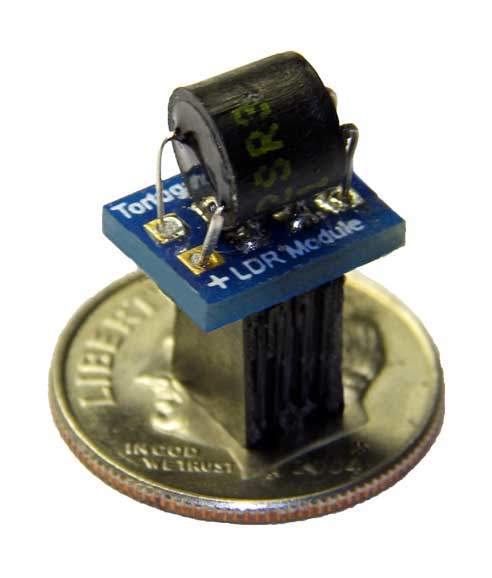
- Easily Replaceable LDR Modules – Our third generation designs allow for unplugging LDR Modules and popping in a new one in. Not unlike a tube. And once a new LDR Module is installed, auto-calibration ensures that optimal attenuation & channel balance is reestablished. Will we see “LDR Rolling” in the future? Who knows. But it’s good to stay flexible.
Fourth Generation Technology – The V25
In April 2017 we released a new updated version of our LDR preamp controller, the LDR.V25 or “V25”.
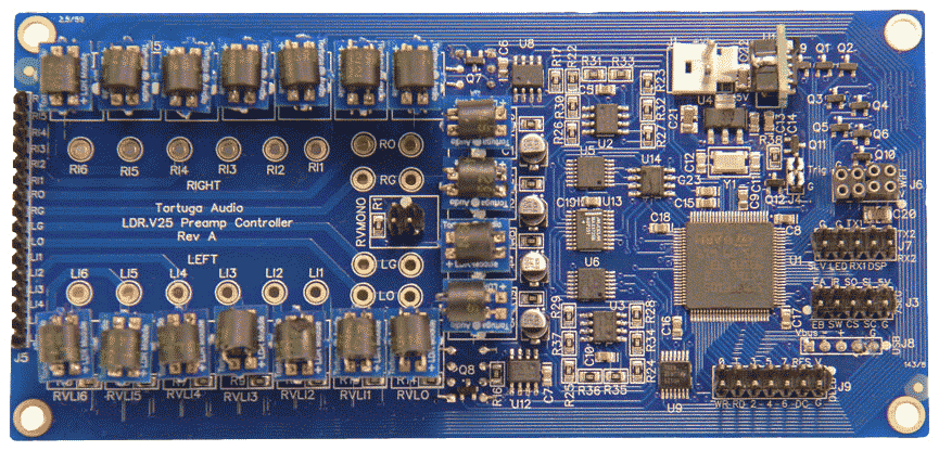
With the V25 we took everything we learned with V2 and its predecessors and redesigned everything from the ground up including both the hardware and the firmware. It’s accurate to say that the V25 is better in every way.
More accurate, more powerful, more flexible, smoother, and it now includes up to 6 switchable stereo inputs (using LDRs as switches) into a single integrated board.
Most importantly, the V25 raises the sonic performance bar and actually sounds even better than ever. Wider sound stage, better dynamics, darker background, the list goes on.
More in depth info on the V25 can be found via this link to our online documentation.
You can purchase a LDR.V25 board here.