
What is impedance?
Simply put, the impedance of an audio device (preamp or amp etc.) is the resistance to the flow of an audio signal either into or out of an audio component. It’s called impedance rather than just resistance because impedance is the effective resistance of a dynamic signal over its frequency spectrum resulting from the complex interactions of simple resistance plus capacitance and reactance. Audio signals are composed of complex frequencies that can span the full range of human hearing from 20 Hz to 20,0000 Hz, thus we use the term impedance. With purely static direct current flow there is only resistance. Resistance and impedance are both expressed in units of ohms or thousands (k) of ohms.
Input impedance with LDRs
In the section on LDR volume control we discussed how volume control works with both potentiometers and LDRs.
If we want to maintain a target of say 20k ohms input impedance, the combined resistance of the series and shunt LDRs should equal at least 20k ohms. However, due to certain limitations inherent with LDRs, we can’t drive the shunt LDR resistance down to zero as we can with a potentiometer.
In order to still have volume control over a 60 dB range, the work around is to increase Rseries such that the combined LDR impedance of Rseries plus Rshunt exceeds our fixed target as we reduce volume into the lower volume range.
This is illustrated in the graph below for a nominal 20k LDR attenuator. The input impedance (green line) starts at 100k at zero volume, drops down to 20k by step 16 (-46 dB) and than remains constant over the remaining attenuation range. Note that the impedance is the sum of Rseries (red line) and Rshunt (blue line) the ratios of which define the attenuation level in dB (black line) at each step.
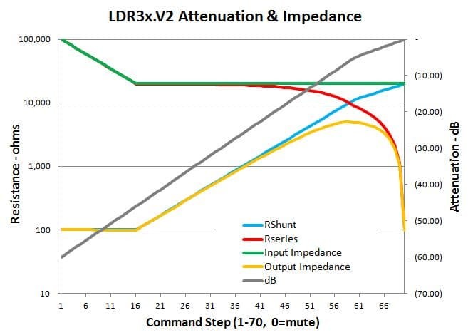
Output Impedance
The output impedance of potentiometers and LDR attenuators is neither fixed nor is it independent from the input impedance. As is clear in the above graph, the output impedance (yellow line) actually varies with each step in the attenuation even as the input impedance remains largely constant.
The output impedance is actually the parallel resistance of the series and shunt LDRs. The output impedance starts at ~100 ohm and remains relatively constant until step 16 and then begins to increase along with the shunt resistance. Output impedance peaks at 25% of the nominal input impedance corresponding to step 59 in this particualr graph which is at exactly -6 dB of attenuation.
There’s no avoiding the varying output impedance shown above when working with potentiometers and LDR based volume controls. While not ideal (you’d like to see low and constant output imedance) the varying output impedance is acceptable in most real world audio applications.