
When LDRs Go Bad
Our experience with LDRs is that very few go bad but those that do tend to go bad very early on in their life often within a few days or weeks of initial operation. If they get through this initial period they tend to last for several years if not indefinitely.
When listening to music, the key symptom indicating that an LDR has gone bad is a permanent shift in channel balance favoring either the left or right side. In some cases a channel’s volume may become fixed while the other channel operates normally. It’s extremely rare for an LDR to fail in such a way that it stops conducting the audio signal completely.
During a calibration cycle, a bad LDR will likely cause the calibration sequence to slow down or stop altogether while trying to calibrate a specific LDR. This is the most reliable way to identify which LDR needs replacing. It’s quite rare for more than a one LDR to go bad at the same time.
LDRx/LDRxB models
Remove Top Panel Screws – Remove the 6 socket head screws/washers from the top panel. Some units may not have these screws. Do NOT try to remove the top panel yet. The top panel is mounted into groves in the side panel and therefore must be slid out towards the rear once the rear panel has been detached.
Remove Rear Panel Screws – Remove the 4 socket head screws located in the 4 corners of the rear panel. Gently drop the rear panel assembly down slightly making room for the top panel to clear the top of the rear panel.
Remove/Slide-out Top Panel – At this point you should be able to slide the top panel towards the rear of the unit. Some panels may be difficult to slide out. Be very patient. Try to gently pull the panel. If the panel is resisting using a small flat screw driver to pry the front edge of the top panel away from the rear face of the front panel. Be careful not to gouge either the top panel or rear panel. Continue to nudge and pull the top panel out the rear of the unit until it’s fully removed.
Reassembly When Done – When you’re done with LDR replacement/maintenance simply reverse the above process. Please use a light touch when sliding the top panel back in place. Don’t force it if it sticks or gets skewed – carefully realign before continuing. Also please use a light touch when reinstalling all the screws since the screws may only be going into relatively soft bamboo material. If a screw gets stripped, remove the screw and panel, and put a few drops of superglue into the hole and give the glue time to fully harden. Then try again.
V2/V25 Models
Remove Front/Rear Panel Screws – Remove the 4 socket head screws/washers from both the front and the rear panels.
Slide-out Assembly – The preamp assembly is attached to a slide-out mounting board that is located in the lower most set of slide rails. Gently withdraw the assembly by pulling the rear panel outwards. While doing so gently reorient and feed the front panel into the enclosure box. Stop withdrawing the assembly once you’ve exposed all the LDRs and can access them with your hand.
Reassembly When Done – When you’re done with LDR replacement/maintenance simply reverse the above process. Please use a light touch when sliding the mounting board/assembly back in place. Don’t force it if it sticks or gets skewed – carefully realign before continuing.
300x.V3 Model
Remove Front/Rear Panel Screws – Remove only the 2 top socket head screws/washers from both the front and the rear panels. Leave the bottom 2 screws in place.
Lift off top enclosure – The enclosure is made up of a symmetrical top and bottom half-shell with a longitudinal split along both sides. Once the 2 top screws on the front and rear panels are removed there’s nothing holding the top shell in place except for friction. Gently lift the top shell up. Do not force it. Wiggle and pry gently. It will come up and off. Please note the front-to-back orientation of the top shell as you remove it. It must go back on the same way or else the 2 shells will not mate properly.
Reassembly When Done – When you’re done with LDR replacement/maintenance simply reverse the above process. Put the top shell back in place and replace the 2 socket head screws in the top corners of both the front and rear panels. DO NOT over tighten theses screws – you might shear them off and/or crack the acrylic front panel. Barely snug is sufficient.
LDR modules 
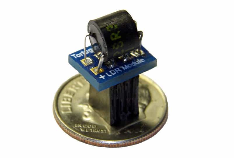
Each LDR Module is a female socketed 4-pin module that is easily removed from the controller board and replaced with a new module. Each LDR Module fits onto a 2×2 male pin header on the controller board.
The LDR Modules are not keyed so there’s four possible ways to plug in a LDR Module but only one correct way. Each LDR Module has a white dot on its small circuit board.
IMPORTANT! – The white dot on the LDR Module must be aligned with the matching white dot located adjacent to each 2×2 male pin header on the controller board.
LDR Identification
The first step in diagnosing and replacing a bad LDR is to familiarize yourself with the identity and location of each of the four attenuation LDRs on the particular model of preamp controller board present in your preamp. There are currently 2 different models of preamp controller board that uses replaceable plug-in LDR modules; the V2 and the V25. These are both discussed below.
The following table is helpful in identifying the 4 LDRs used in volume control that are subject to the calibration process. The calibration sequence is always #1 through #4. The V2 and V25 boards differ slightly in the physical locations of each of these LDRs.
| LDR Function | Calibration Sequence | ** V2 ONLY ** Circuit Board Label | ** V25 ONLY ** Circuit Board Label |
|---|---|---|---|
| Right Series | #1 | RV3 | RVRSE |
| Right Shunt | #2 | RV4 | RVRSH |
| Left Series | #3 | RV1 | RVLSE |
| Left Shunt | #4 | RV2 | RVLSH |
The V2 and V25 preamp controller boards are shown below with each of the 4 LDRs identified. The above table cross-references the various ways of identifying each LDR.
It is most useful to identify the LDRs in terms of their calibration sequence (#1 through #4) since this sequence is shown on the preamp display during the calibration process.
V25 preamp controller
During calibration, a V25 preamp controller with dual 7-segment displays will show the LDR # in the left display and the calibration step # in the right display. A V25 goes through steps 1-99 for each LDR.
A V25 preamp controller with and OLED display offers considerably more status information during the calibration process. Each of the 4 LDRs goes through a 3 phase calibration process referred to as VLo, VRef, and Cal. Each of the 4 LDRs first goes through the brief VLo phase. Then, starting again with LDR #1, each LDR goes through a brief VRef phase immediately followed by the main Cal phase. The Cal phase will take several minutes going 100 individual calibration steps for each LDR.
When a specific LDR (1, 2, 3 or 4) goes sufficiently out of spec, the calibration process in the V25 is most likely to fail to progress through either the VLo or VRef phase. Less common is for the V25 calibration cycle to stall out somewhere in between step 1 and step 99.
Note that the V25 also uses LDRs for input channel switching and also for isolating the output signal during calibration. Those LDRs are identified below but are on/off only and are not involved in the calibration process.

V2 preamp controller
During calibration, a V2 preamp controller with dual displays will show the LDR # in the left display and the calibration step # in the right display. A V2 goes through steps 1-70 for each LDR.
When a specific LDR (1, 2, 3 or 4) goes sufficiently out of spec, the V2 will have a difficult time starting or completing the 70 step calibration sequence for that LDR. The calibration process may stall out at step 1, step 70, or at some intermediate step between 1 and 70. When this happens, note the LDR # in the left display. This usually indicates the LDR needs to be replaced.

Replacing A Bad LDR
To replace an LDR first remove power from the preamp. Then simply remove (unplug) the suspected bad LDR (the one at which calibration stopped progressing) and replace it with a new LDR Module.
IMPORTANT! – When installing a new LDR module make sure that the white dot on the LDR module circuit board is on the same side as the white dot on the controller circuit board. The LDR modules are NOT keyed so it’s possible to plug the module in 4 different ways but only 1 is the correct way.
After a new LDR module is installed, you should immediately run the unit through a cycle of calibration. This will rebuild the attenuation table for your current impedance setting/level and in doing so will measure and incorporate the unique performance curve of the new LDR module.
LDRs operate as pairs of Series & Shunt resistors with one pair for the Right channel and the other pair for the Left channel. If, after replacing a faulty LDR, the calibration process still slows down or halts at the same LDR as before, it’s likely that it’s companion LDR is the cause of the problem. In this case, remove the new LDR and put the old LDR back. If calibration stopped at LDR #1, replace LDR #2 instead. If calibration stopped at LDR #2, replace LDR #1 instead. If calibration stopped at LDR #3, replace LDR #4 instead. If calibration stopped at LDR #4, replace LDR #3 instead. Then run calibration again. Chances are good that calibration will now run to completion normally. In rare cases you may find you have to replace both the Series and Shunt LDR Module for a given channel in order for calibration to work properly.
Special Considerations For Balanced Preamps
Balanced preamps utilize 2 preamp controller boards. When facing the front of the preamp looking towards the rear of the preamp, the rightmost controller board is designated as the primary (master) and the left board is designated as the secondary (slave). All user control inputs are handled by the primary board which in turns controls the secondary board.
For purposes of diagnosing LDR replacement in balanced preamps, it’s best to view the left/right channel labels on each controller boards as NOT necessarily being synonymous with the Left and Right stereo channels and simply think of them as LDRs #1 through #4 in terms of their calibration sequence.
