
A DIY preamp controller/attenuator
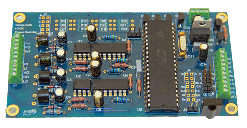
The LDR3x (aka the “V1”) is a preamp controller in the form of a partially populated 2.5 inch by 4.7 inch printed circuit board that is marketed to the do-it-yourself (DIY) audio enthusiast who wishes to build their own preamp.
Insofar as the LDR3x lacks a power supply, controls or enclosure it is neither a complete finished audio premap nor is it a comprehensive kit.
Once connected to an external power source (not included), the LDR3x can accommodate one (1) single-ended audio input without any additional equipment and up to three (3) inputs when interfaced with an external input relay board (not included).
The LDR3x is sold with an uninstalled infrared receiver module that the user can either solder to the LDR3x board or locate external to the board via user provided wiring.
The LDR3x can be controlled by the Tortuga Audio Remote, the Apple Remote and/or Encoder all of which are optional and not included. The LDR3x also has several unique control inputs that are enumerated and explained in sections below.
The LDR3x is part of the Tortuga Audio family of LDRx passive preamps. Please refer to documentation under LDRx Passive Preamplifier for more information that applies equally to the LDR3x.
Two versions | master vs. slave
The LDR3x comes in two versions: a Master and a Slave. The Master operates as a standalone passive preamp for single-ended unbalanced inputs. The Master is also used for balanced audio. The Slave is only used with balanced audio.
The LDR3x can be configured to handle balanced audio using two different approaches: Master/Slave boards or Dual Master boards. In either case both boards (Master/Slave or Dual Masters) are custom matched to have identical matching attenuation curves.
Master/Slave approach
The Master Board is designated for the Right Channel and the Slave Board handles the Left Channel. Only the Master Board is used for control interfaces. The Master Board is physically connected to the Slave Board via a 2×5 pin IDC ribbon cable and the Slave Board operates synchronously with the Master Board. The Slave Board is identical to the Master Board except the Slave Board doesn’t have its own microcontroller, on board 5 VDC power regulator, J2 or J6 terminal connectors.
Dual Masters approach
Alternatively, balanced inputs can be accommodated with a pair of specially matched dual LDR3x Masters. The wiring is the same as with the Master/Slave approach, but each Master Board operates asynchronously from the other (the one doesn’t know what the other is doing). The IR Receivers of both units must have clear “line of sight” to the IR Remote. This approach only works when using a Remote. To initially synchronize the Dual Masters, ramp both LDR3x units down to zero volume, then raise volume to suit using a single Remote as you would with just a single LDR3x. Both LDR3x units will remain “virtually synchronized” with normal raise/lower volume commands from the Remote. Should they become out of balance, repeat the synchronization process.
Audio connections | terminal J1
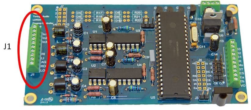
J1 is a 10 position, 0.1 inch pitch screw terminal connector for interfacing the LDR3x with the user’s audio inputs and outputs plus optional external input relay selection board.
| Label | Type | Function |
| In1 | Output | Input selector – sinks relay current to ground when on |
| In2 | Output | Input selector – sinks relay current to ground when on |
| In3 | Output | Input selector – sinks relay current to ground when on |
| nc | No connection | |
| nc | No connection | |
| RI | Audio | Right channel audio input from selected input source |
| LI | Audio | Left channel audio input from selected input source |
| AG | Audio | Audio ground/common |
| RO | Audio | Right channel audio output to amp |
| LO | Audio | Left channel audio output to amp |
Input selectors
Terminals J1-In1, J1-In2 and J1-In3 allow the LDR3x to be interfaced with an external input select relay board (not provided/sold by Tortuga Audio). Each of these 3 control signals provides an NPN current sink to ground when activated. They can be activated via Remote and/or via control inputs to J2 including Encoder (see sections Control Inputs & Outputs (J2) below for more details).
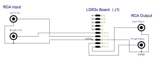
Single ended wiring
The simplest configuration is a single unbalanced audio input (via RCA jack) as shown in the diagram below. The Right Input terminates to J1-RI and the Left Input terminates to J1-LI. Similarly, the Right and Left Outputs terminate to J1-RO and J1-LO respectively. The common audio ground terminates to J1-G.
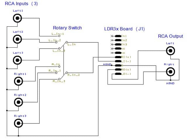
Selecting from multiple inputs can be implemented via a manual double pole rotary switch as shown in the diagram below. Ultimately, the wiring of input and output to the LDR3x is done the same as with a single input except you’re interfacing with the output of the rotary switch instead of the RCA input jacks.
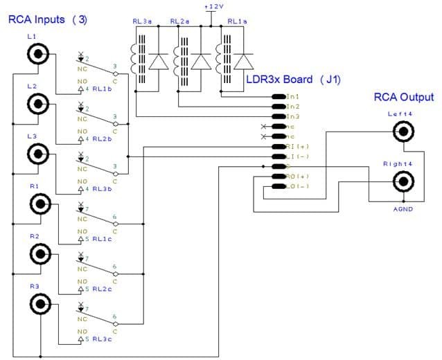
The LDR3x can be interfaced with an external relay board for remote switching of up to 3 input channels as shown below. With up to 3 relays tied to power supply (typically +5V or +12V), the relays are energized (switched to grounded) by the LDR3x board via J1-In1, J1-In2 and J1-In3 respectively. This approach allows you to use the IR Remote, Encoder, or push button inputs to have the LDR3x switch the input relays.
Further detail on the various control options are covered in section Control Inputs & Output that comes immediately after this section.
Balanced wiring
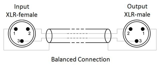
Balanced audio is more complex than unbalanced (single ended). Each balanced channel has 3 (vs. just 2) pin connection; +signal, -signal and ground. The balanced signals except they are 180 degrees out of phase with each other. Balanced audio utilize 3-pin XLR connectors. Depictions of XLR connections can be confusing because the pin numbers look different depending on whether you’re looking at a female (input) or male (output) XLR connection and also depending if you looking at the front or rear of each gender.

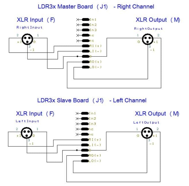
The diagram below shows the balanced input/output connection to the LDR3x for a single input system. For multiple input systems, follow the same guidelines as described above for unbalanced audio. The Master handles the right channel and the Slave handles the left channel. Pin 1 is the pass through audio ground. The input +signal (Pin 2) is connected to J1-RI and the -signal (Pin 3) is connected to J1-LI. Similarly, the output +signal (Pin 2) is connected to J1-RO and the -signal (Pin 3) is connected to J1-LO. The input/output wiring is the same for both the right (Master) channel and the left (Slave) channel.
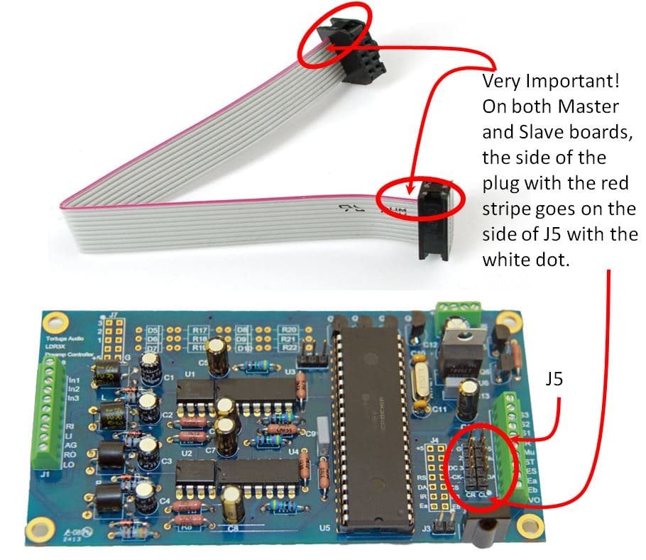
The Master board connects to its Slave board via a 2×5 pin IDC ribbon cable. The ribbon cable sockets connect to the J5 header pins on both boards. Please note the proper alignment of cable to the J5 header as shown in the pic below (only Master board is shown).
Control interface | terminal J2
J2 is a 10 position , 0.1 inch pitch screw terminal connector for interfacing with user’s control inputs and preamp status output as summarized in the list below and further explained in the following sections.
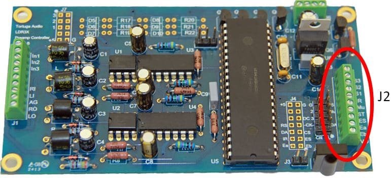
J2 provides the control interface to control all functions of the LDR3x via a combination of inputs including push buttons, encoder, IR Receiver, and analog volume pot. It also provides a single status output for driving an LED Status light.
Control via J2 is optional and can be in addition to or in lieu of control via the Tortuga Remote or Apple Remote. Control inputs via J2 and Remote are complimentary and not mutually exclusive with the exception of controlling volume via analog pot input (J2-VO) which disables volume control via both Remote and Encoder (more detail on this exception below).
Errata: Inputs J2-S1 & J2-S3 are mislabeled (reversed) on version Rev 0.B of the LDR3x board.
The diagram below illustrates how to implement all the control interfaces available via J2. Each of these are discussed below.
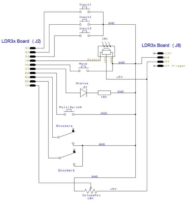
J2-S1, S2 & S3 | input select
These three push button inputs allow the user to select from up to 3 inputs. As shown in the diagram above the 3 pushbuttons terminate to J2-S1, J2-S2 and J2-S3 respectively. The other leg of each pushbutton is connected to common ground (J6-G). Selecting from multiple inputs requires the LDR3x be interfaced with an appropriate input relay switching board (not currently sold by Tortuga Audio) and that the input relay switching board be interfaced with J1-In1, J1-In2 and J1-In3 respectively. Input selection via S1, S2 and S3 can also be implemented using a 3-way single pole rotary switch. S1, S2 and S3 are prioritized such that if all 3 switches were to be pressed (pulled low to ground) simultaneously, S1 will win. If only S2 and S3 were pressed simultaneously, S2 would win.
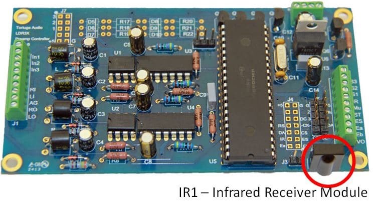
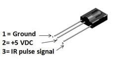
J2-IR | IR receiver
The LDR3x is supplied with a high performance 38 khz infrared receiver module (IR1). The IR1 is supplied loose and not installed. The picture above left shows the IR Receiver installed on the board. The picture above right shows the IR Receiver and its 3 pin connections. Incorrect wiring of power to the IR Receiver will immediately destroy it. You have the option of soldering the IR1 into the LDR3x board immediately next to J3. Alternatively, the user may remotely locate the IR Receiver external to the LDR3x board. If you locate the IR Receiver external to the LDR3x board, pin 1 must be connected to common ground (J6-G), pin 2 must be connected to +5 volt power (J6-+5) and pin 3 must be connected to the J2-IR. To make these connections, you will have to solder (or otherwise connect) extension wires to the IR Receiver pins and terminate these to the LDR3x. Regardless of where you choose to locate the IR Receiver, it must have reasonable line-of-sight access to the handheld IR Remote. The most common approach is to have the IR Receiver be “looking out” from the front panel of whatever enclosure you use to house the LDR3x.
J2-MU | Mute
This push button input toggles the Mute/UnMute status of the LDR3x. The other leg of the Mute pushbutton must be connected to common ground (J6-G).
J2-ST | Status LED
This is only output on terminal J2 and when connected to an LED provides status information on the LDR3x. The positive (+ long) end of the LED connects to J2-ST which provides +5 V when the LED is turned on. The negative (- short) leg of the LED connects to common ground (J6-G). In most cases you’ll want to place a resistor in series with the Status LED to limit current (and brightness) through the LED. We recommend a 10-30k resistor but this will ultimately depend on the specifications of your LED and your desired brightness.
J2-ES, J2-Ea & J2-Eb | encoder inputs
These 3 inputs are for interfacing the LDR3x with the Encoder. J2-ES is a push button switch multi-purpose switch (Multiswitch) that can act as a power on/off toggle switch, mute/un-mute toggle switch and balance-mode-select switch. While the MultiSwitch input can be implemented by itself, it’s intended to be implemented in conjunction with the rotary Encoder which has an integral push button switch. J2-Ea and J2-Eb are for connecting the “A” and “B” legs of a rotary encoder. The common leg of the rotary encoder must be connected to common ground (J6-G).
The LDR3x was designed and tested to work with the Alps EC11 series of encoders and more specifically the model EC11B15242AF although probably any of the EC11 encoders (or equivalent) will work. Additional info on the EC11 encoder can be found in the Appendix to this manual.
J2-VO | volume control potentiometer
This input allows the LDR3x volume to be manually controlled using a conventional potentiometer (“pot”). Connect one leg of the pot to 5 VDC board power via J6-+5 and the other leg of the pot to ground via J6-G. The pot wiper (center terminal) should be tied to the J2-VO terminal. 0V = min volume (muted) and 5V = max volume. Ideally the pot should have a linear taper since the LDR3x already has its own programmed logarithmic audio taper. Since the pot acts as a voltage divider it can be any nominal resistance but we suggest 5K ohm or greater to limit current draw.
Volume control via a J2-VO pot is enabled via jumper JP1 on the LDR3x board as shown in the picture to the right. Jumpering the 2 right-most pins (or just the 2 pins on boards with only 2 pins) enables this volume control mode.
Special Notes
Wiring Pot Backwards: If clockwise rotation of the pot results in decreasing volume and counterclockwise rotation increases the volume, then simply swap the +5V and Gnd inputs to the pot legs.
Remote/Encoder Volume Control Disabled: Enabling Volume control via a pot input to J2-VO will disable volume control from both the Infrared Remote and Encoder.
Power | terminal J6
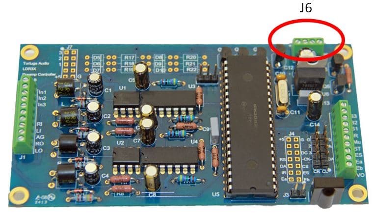
The LDR3x is NOT sold with its own power supply. The user must supply their own 12 VDC or 5 VDC power source to power the LDR3x.
J6 is a 4 position 0.1 inch pitch screw terminal connector for powering the LDR3x with either 12 VDC or 5 VDC power and also provides a 12 VDC Trigger output. Each of the 4 connections is explained below.
J6+12 | main power
The recommended approach is to power with LDR3x with 12 VDC via terminal J6+12 although the LDR3x can also be powered with 5 VDC via terminal J6+5. The 12 VDC power supply can be a switch mode power supply or linear power supply (see the Specifications below for details). While not required, we recommend a regulated 12 VDC power supply to avoid problems with the 12 Volt Trigger Out. The LDR3x takes the 12 VDC input and steps it down to a regulated 5 VDC to power the DCU and the LDRs. The regulated 5 VDC is also available as a power source for control devices via terminal J6+5. The 12 VDC is also used to power the 12 Volt Trigger Out feature.
J6+5 | main/control power
When the LDR3x is powered with 12 VDC, regulated 5 VDC is available via J6+5. When the LDR3x is powered with +5 VDC instead of 12 VDC , the user connects a 5 VDC source to the J6+5 terminal. The 5 VDC power soucr MUST BE REGULATED! If the LDR3x is powered via a 5 VDC external power source, the 12 VDC Trigger Output (J6+12T) will not be functional.
J6-G | ground
The power supply ground MUST be connected to J6-G in order for the LDR3x to function properly.
J6+12T | 12 volt trigger out
When powered by a 12V DC power source, the LDR3x will generate a switched 12V DC trigger output on terminal J6-12T when the LDR3x is turned on. This output can be used to turn on and turn off other audio components equipped with 12 V triggered inputs. This feature is not operational if the LDR3x is powered from a 5 VDC source.
