
An IO board for the LDR3x (V1)
The IO3 (input/output) Relay Board can be interfaced with the LDR3x Preamp Controller Board (versions 1 or 2) to enable switching between up to 3 audio input signals. There are 2 versions of the IO3 board: the original IO3.1D and the current IO3.2A. Pictures of both versions are shown below. The key differences are summarized in the following table.
| IO3 version 1 | IO3 version 2 | |
| Feature | ||
| Solder pads for input/output interface with LDR3x board | Yes | No |
| Dimension | 2.5″ wide x 1.7″ tall | 2.84″ wide by 1.4″ tall |
| Mounting holes | 4 corner holes | 3 interior holes |
| J2 pin interface with LDR3x board | 1×5 pin header | 2×5 pin header |
| Output solder pads | 2 | 1 |
Please note that the IO3 Version 2 board also has mounting spots/pads(6) for 2 relays plus a Q1 transistor however these items are intentionally not installed or used. These items are not installed or used in the IO3.2 because they introduced an unacceptable level of switching noise when used.
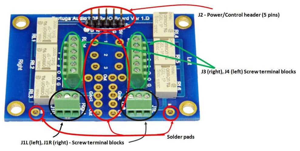
IO3 Version 1 Board
The IO3 interface points are identified in the IO3.V1 photo below (not to scale!). Please note that the IO3 is symmetrical in that the left side of the board (as viewed below) handles the right channel and right side of the board (as viewed below) handles the left channel. Thus, left/right channel signals do not intermingle on the board.
IO3 Version 2 Board
The IO3.V2 board is shown below. Version 2 is superficially and functionally similar to the version 1 board.
Of particular note are the requirement of installing the two jumper wires (shown in red below) in lieu of the relays that are not used. Some IO3.2 boards were shipped without these jumper wires. The jumper wires connect the output signals from the J1R and J1L terminal blocks to the the J3/J4 output screw terminals and associated output solder pads.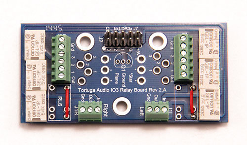
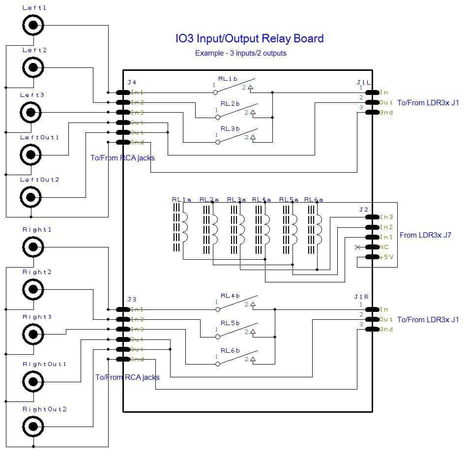
Wiring Diagram
The diagram below illustrates a typical scenario of connecting the IO3 to 3 single-ended RCA input signals and 2 RCA outputs (in parallel). Each left and right input signal connects to its own single-pole relay. There are 6 relays for 3 left channel signals plus 3 right channel signals. The relays are energized by the LDR preamp controller board by connecting a cable from the controller to the IO3.J2 pin header. The +5V provided by the LDR preamp controller provides powers to the relays and each pair of relays is energized by the preamp controller which connects the corresponding control line (In1, In2 & In3) to ground.
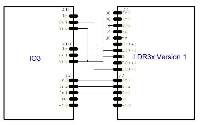
Connecting to LDR3x (V1) board
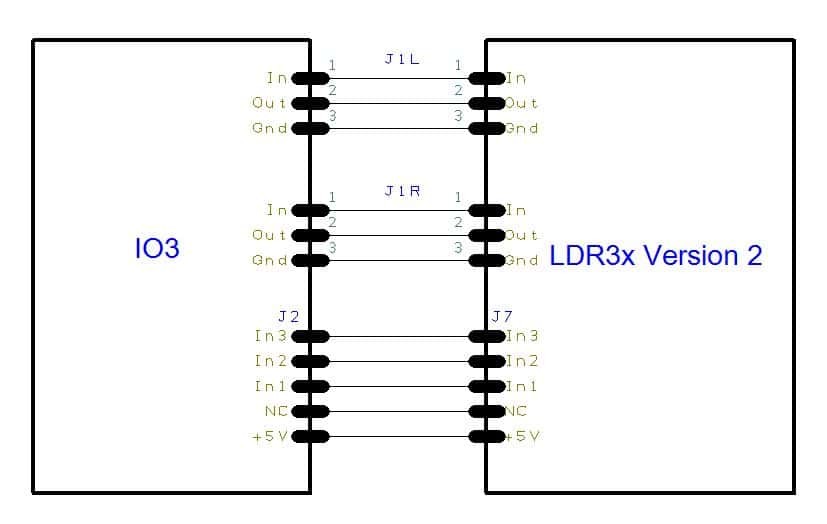
The diagram below shows how to connect the IO3 to a Version 1 LDR preamp controller board. J1L and J1R of the IO3 connect to the corresponding J1 terminals of the LDR3x. Be careful to connect left with left, right with right, input with input and output with output. It’s all too easy to make a mistake with the wiring. Also note that with the Version 1 LDR controller the left/right channel grounds are connected together at the J1 terminal of the LDR board. Lastly, while not shown in the diagram below, you may alternatively connect J2.IO3 terminals In1, In2 and In3 to the corresponding J1.LDR3x terminals of the same name instead of using J7.LDR3x. However, you still need to connect the +5V power as shown.
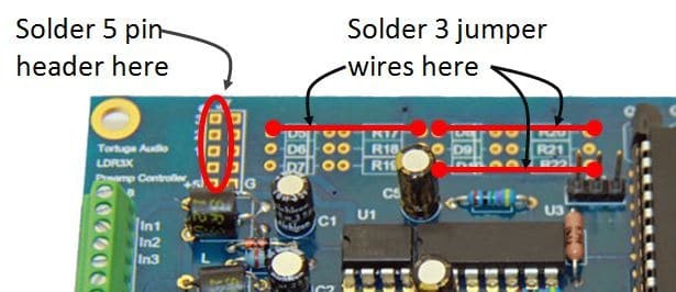
Version 1 LDR preamp controller boards require certain modifications to work with the IO3. These are simple to do. First, you will need to install/solder a 5 pin header in the left side of J7 as shown in the LDR.V1 picture below. You also need to install 3 jumper wires between the solder pads as shown below. Just in case the photo isn’t clear on this, the jumpers need be connected as follows: a) between right pad of R20 and left pad of D8; b) between right pad of R22 and left pad of D10; and, c) between right pad of R17 and left pad of D5.
Connecting to V2/V2.1 controller board
The diagram below shows how to connect the IO3 to Version 2/2.1 of the LDR board. J1L and J1R align with each other both physically as well as schematically. No modifications are required to he LDR.V2 board to connect J2 to J7.
Solder pad vs. screw terminals
Most signals shown above (except for +5V power) can be connected to the IO3 via solder pads instead of using the screw terminals. While not as flexible and maintenance friendly as screw terminals, soldered signal connections are simply more reliable and maintenance free. Please note that the IO3 Version 2 board does not provide solder pads for connecting the audio signals to the LDR board.
