
Variations
The following instructions are intended for the LDR3.V25K Passive Preamp kit. Earlier versions of this kit included dual 7-segment displays. These were later replaced with the newer OLED display. The instructions herein have information for both display types. A balanced version of this kit was also offered. There are references to a balanced version in theses instructions. Regardless of display type or single ended vs balanced, most of the information is applicable to all kit variations.
Assembly overview
Assembly of the LDR.V25K kit is fairly straightforward insofar as all the electronic components have already been installed on their circuit boards. Most of the work is a combination of mechanical assembly, connection of cables, and wiring. The cutting, stripping and soldering of the various wires is probably the most challenging aspect of the assembly process.
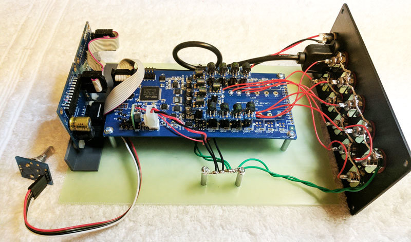
When you’re almost done the final assembly will look something like the pic below. You will then slide this assembly into the enclosure and attach the front and rear panels to the enclosure to finish the job.
We believe the instructions and guidelines provided are adequate to assemble the kit successfully but we remain open as always to suggestions on how to clarify and improve this information.
Enjoy your project!
Balanced version
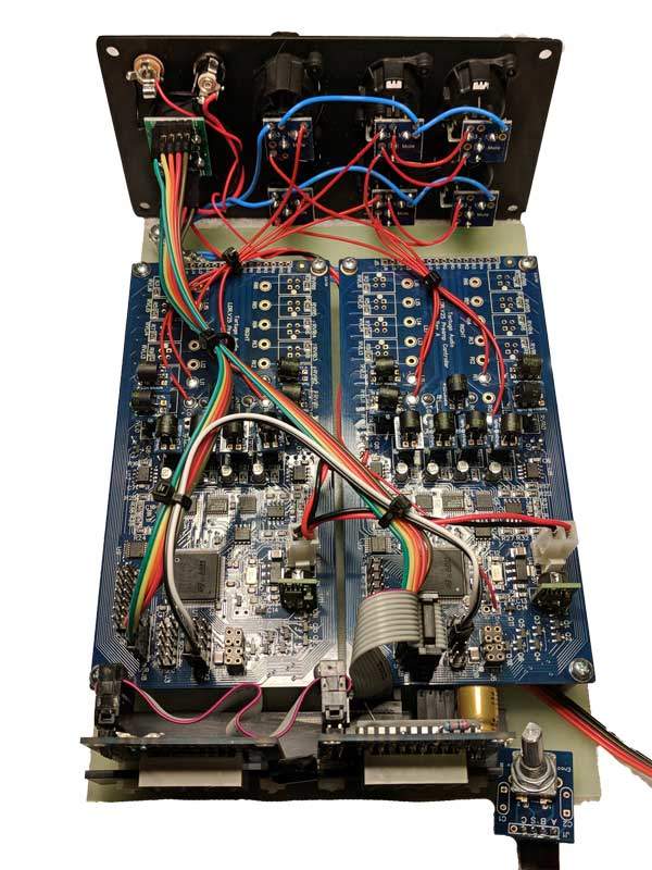
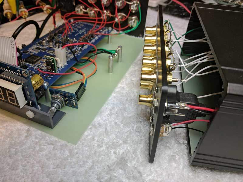
The assembled balanced kit differs from the single-ended kit as follows and as shown in the picture below (picture has 7-segment rather than new OLED display but is otherwise correct) :
- The balanced kit uses a different rear panel with XLR type jacks with 1 set of XLR inputs and 2 sets of XLR outputs.
- There are 2 V25 boards used instead of just 1.
- The rear panel for the balanced kit uses a XLR shaped dual USB port with 5-wire USB cables from the USB port to each of the 2 V25 boards
- The V25 board on the right is the master board to which the 2 OLED display cables are attached.
- The Star Ground buss bar is located in the left rear corner of the Mounting Board rather than the center right area.
Install standoffs & display bracket to mounting board
There are six (6) standoffs as shown below. 1-2-3-4 are for mounting the Controller Board. 5-6 are for the Star Ground.
Make sure you leave standoffs 1-2-3-4 somewhat loose at this point. You will want some flexibility in these standoffs when attaching the Controller Board later on.
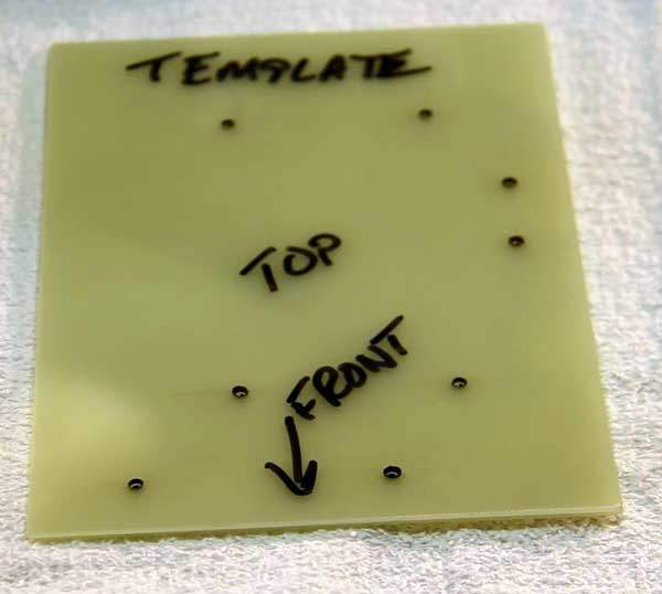
The Display Bracket mounts to the front of the Mounting Board as shown with 2 screws/nuts (ignore those 3 white lines for now). The 2 screws must come up through the bottom of the Mounting Board through the bracket such that the nuts are on the top as shown.
Make sure the nuts are reasonably tight. It’s very difficult/awkward to access these nuts later.
Make sure the Display Bracket face with the 4 drilled holes is facing forward and not backward.
Balanced version
The balanced kit differs from the single-ended kit as follows:
- There are 2 V25 boards each mounted side by side on the Mounting Board rather than just a single V25 located centrally as shown.
- The mounting pattern of standoffs are repeated for each of the 2 V25 boards.
- The star ground standoffs are located in the left rear corner of the Mouting Board.
7 segment | install display assembly to bracket
- Find 2 white threaded nylon rods and screw on a nut to only one end of each rod as shown to the right.
- Insert the rod with nut through the back side of one Display Module through each of the bottom two corner holes in its PCB such that the two bare rods are now facing you and the nuts are behind the display PCB.
- Slip a white nylon spacer over each rod such that the spacer is now against to front side of the PCB. Some kits may not have spacers and if so use nylon nuts as the spacer instead.
- Next thread the bare nylon rod ends through the two holes in the Display Bracket from the backside such that the spacer is now up against the back side of the Display Bracket and the two bare rods are pointing out the front.
- Thread a nut on to each rod and tighten until the nut-pcb-spacer-bracket-nut “sandwich” is now snug (see next pic below)
- Repeat 1-5 for the other Display Module
- Attach the ribbon cable between the master and slave Display Modules.
In some cases the “spacer” will be another nut. In which case make sure you tighten the the 2 nuts on other side of the Display Module before proceeding to mount the displays to the Display Bracket.
Make sure the master Display Module is on the right side and the slave Display Module goes on the left side. The master Display Module is the one with the most electronic components on its PCB whereas the slave has only a single 2×5 pin header and a 2 digit display.
Try to keep the ribbon cable and the Encoder cable attached to the master Display Module while mounting it to the Display Bracket. It’s much more difficult to attach these cables after the master Display Module has been mounted to the Display Bracket.
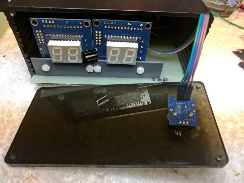
At this point the Display Module assembly should look something like the picture below. Note that the threaded nylon rods now need to be nipped off using which is easily done with any plyer style cutter.
7 segment | install IR receiver module to right display
 Normally we try to install the IR receiver module on the right Display Module before we ship the kit. In the event the IR receiver module is shipped loose, here are the instructions for mounting the IR receiver module.
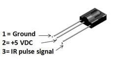
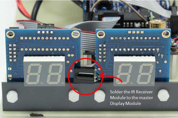
The IR receiver module needs to be soldered into the right Display Module (the one on the right) in its lower left front corner as shown in the picture below. The 3 pins of the IR insert into the 3 holes in the right Display Module. You should insert the IR far enough into the holes so that you can bend the IR leads to the left leaving it IR facing out towards you.
Make sure before soldering that there is room to bend the IR Receiver Module to the left such that it does not block or interfere with the adjacent Display Module.
Make sure you clip off the excess leads of the IR after it’s been soldered in place. Do this now before proceeding because it will be difficult to access them later.
OLED | mount display assembly to bracket
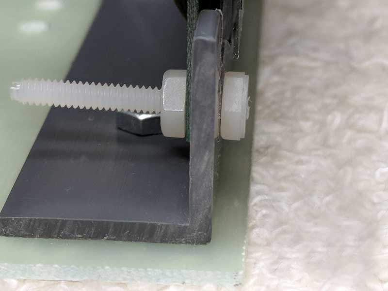
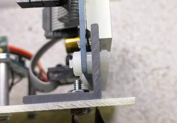
The Display Assembly consists of the OLED display mounted to a gray plastic angle Display Bracket. The Display Bracket attaches to the Mounting Board via two (2) metal screws with nuts as shown in the picture above. The OLED display is then attached to the to the Display Bracket using a pair of white threaded nylon rods and nuts.
Please note that later version of the OLED display assembly did away with using 2 ribbon cables and only have a single ribbon cable connecting the display assembly to the controller board.
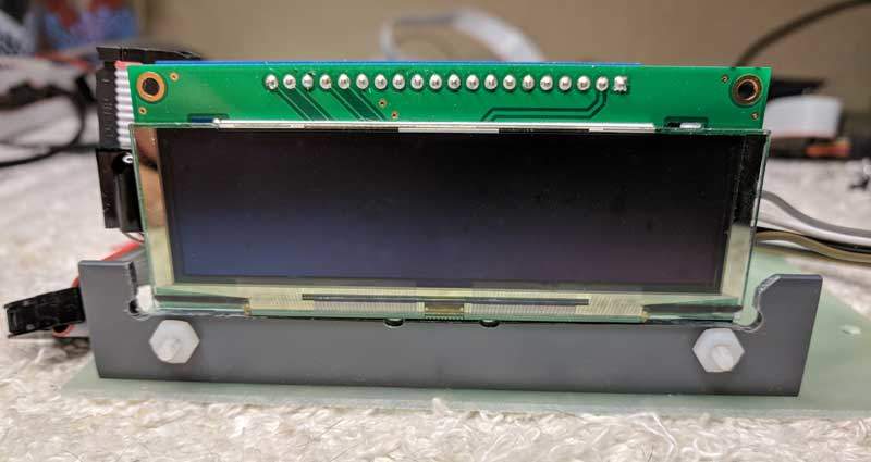
The image below shows a front view of the Display Assembly with the OLED display attached to the Mounting Bracket via the two (2) nylon rods with nuts. Here the nylon rods are shown extending out past the nuts.
The nylon rods must be cut flush with the nuts so that the nylon rods do not interfer with the Front Panel.
The image below shows the details of the OLED display mounted to the Display Bracket with the threaded nylon rod. From front to back you have the “sandwich” of nut, bracket, OLED board, and nut. Note how the nylon rod has been made flush with the front face of the front nut. The excess threaded rod pointing to the rear of the mounting board can be left as is or optionally cut off.
Kits with the OLED display have the IR Receiver Module already mounted to the left side (as you face the display) of the OLED display adapter board so no further install is required. The IR Receiver Module must be oriented to look forward with a clear line of sight through the acrylic front panel.
Install controller board
Mount the V25 controller board on the 4 standoffs that you previously attached to the Mounting Board. Secure each corner with a #4 screw provided.
Note that the pic below does not show the Display Assembly already installed. Note also the 2 Star Ground standoffs near the top of the mounting board.
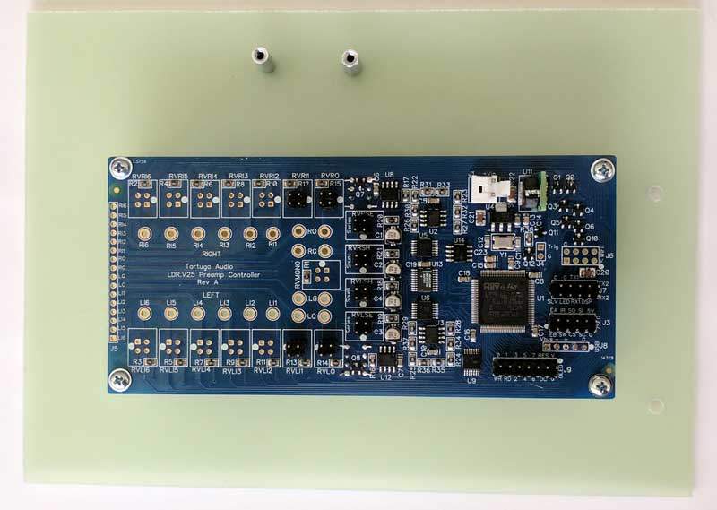
Verify that the screws to the controller board standoffs are tight on both the board side and on the underside of the Mounting Board.
Balanced version
The balanced kit differs from the single-ended kit as follows:
- There are 2 V25 boards each mounted side by side on the Mounting Board rather than just a single V25 located centrally as shown.
- The balanced version uses a total of 8 standoffs for the 2 V25 boards.
OLED | connect display to V25 board
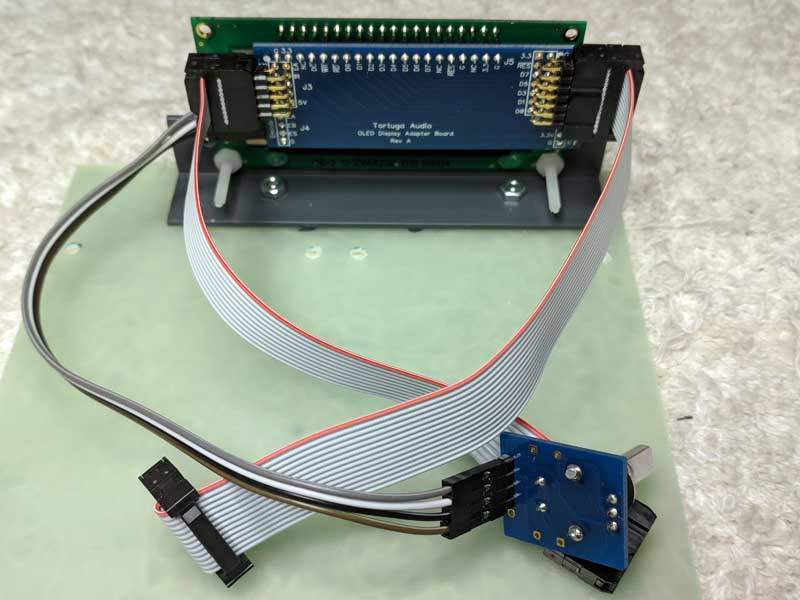
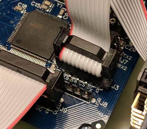
The OLED Display Assembly connects to the V25 board via either 2 ribbon cables as shown below (earlier kit versions). Later versions use only a single ribbon cable to J9 only and the J3 heade is no longer present on the V25 board.
The larger 2×7 ribbon cable is the OLED cable proper and transmits data to the OLED display. The second smaller 2×5 ribbon cable carries the control signals coming from the IR Receiver Module and the Encoder Module. Later versions consolidated all these signals into the single larger ribbon cable that connects to J9.
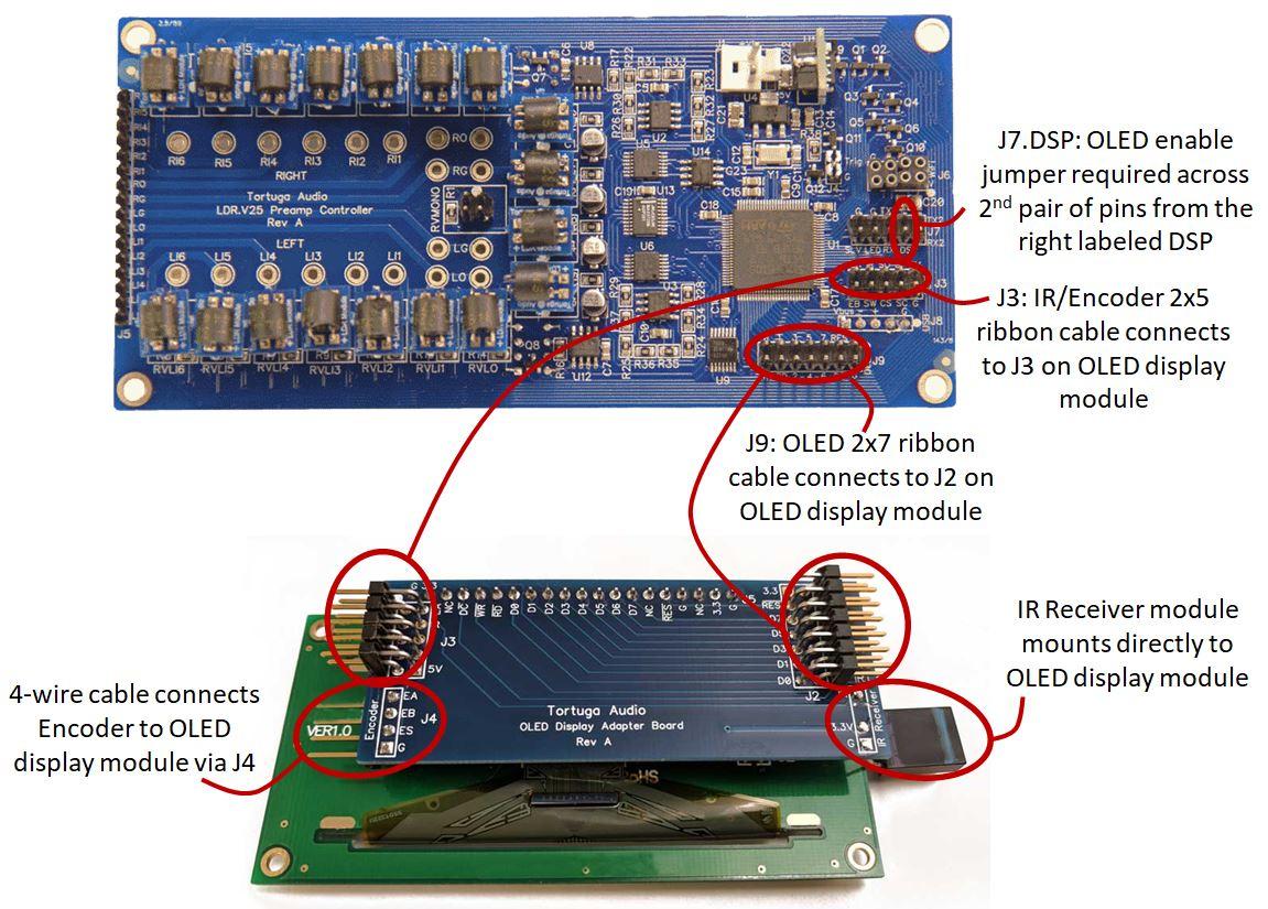
Please note the correct alignment of the red stripe on the ribbon cables at both ends. You should make doubly sure that the red stripes are oriented as shown in the 2 pictures below.
Also note that the pics shown above and below are for the Rev A OLED interface board. Subsequent revisions of the OLED display board may not require the smaller second 2×5 pin ribbon cable.
Star ground
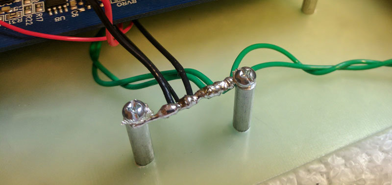
The 2 remaining standoffs on the Mounting Board are for creating the Star Ground point. All ground connections will terminate at the Star Ground.
Strip off the insulation on a 3-4″ length of either the heavy black or green wire. Thread a #4 screw into both standoffs approximately half way leaving room for the wire between the screw head and the standoff. Suspend the stripped wire between the 2 standoffs as shown in the pic below. Put one full turn of the stripped wire around each screw. Then tighten the screws so that the bare wire is now firmly suspended between each standoff. Use wire cutters to trim off excess wire.
Rear panel | RCA jacks
Follow the steps below to install the standard kit RCA jacks into the rear panel.

Step 1 – Insert the RCA jack threads first into the rear panel from the labeled side. Make sure the jack has its white hole alignment washer (not the #2 washer) and that the raised inside edge of the alignment washer is facing towards the rear panel as the jack is inserted.
Step 2 – Slide the white washer onto RCA jack
Step 3 – Thread 1st nut on to RCA jack and tighten it down. Make sure to center the jack in the panel since the panel holes are larger than needed for the standard jacks in order to also accommodate the larger optional Cardas jacks. The threads of the jack should not be touching the panel.
Step 4 – Slide ground ring on with tab facing up towards the top of the rear panel.
Step 5 – Tighten the 2nd nut on to RCA jack while holding the ground tab facing towards the top edge of the panel.
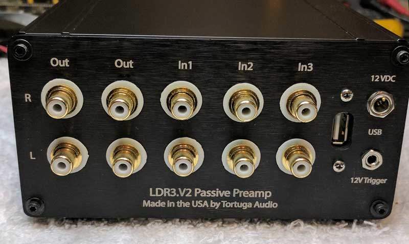
Repeat the RCA jack install steps above for each of the 10 RCA jacks. When completed the 10 jacks in the rear panel will appear as shown below.
Balanced version
The balanced kit differs from the single-ended kit as follows:
- The balanced kit uses a different rear panel with 1 XLR input and 2 XLR outputs (6 total) where each jack is fastened to the rear panel via 2 screws.
Rear panel | power, trigger & USB
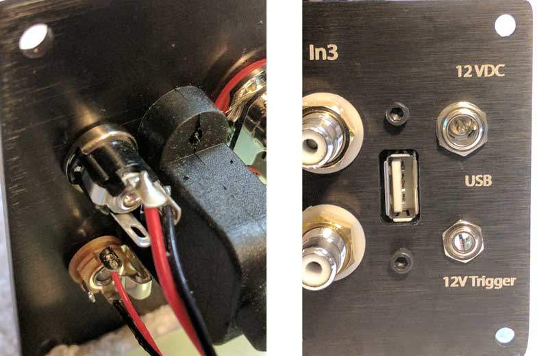
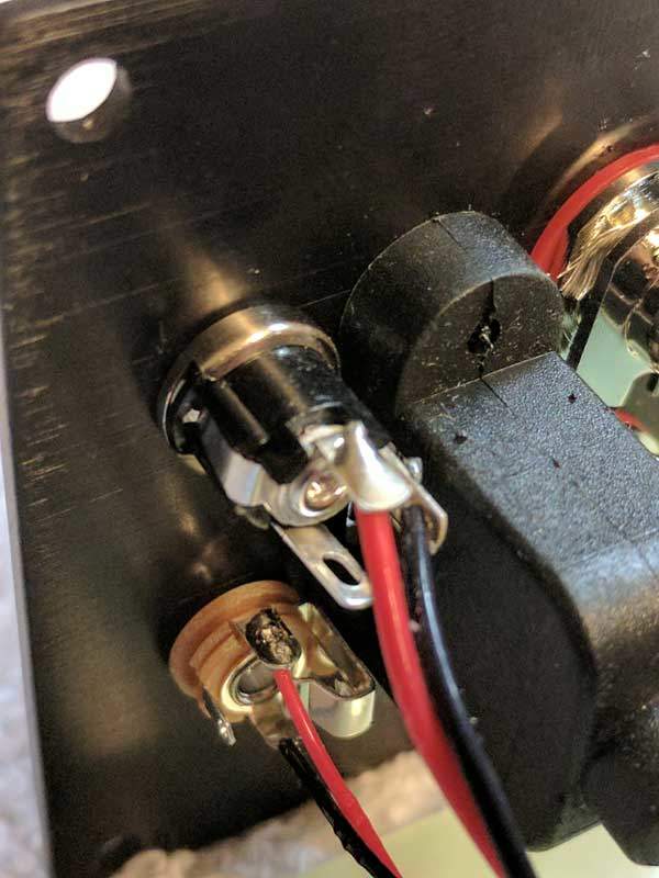
After installing the 10 RCA jacks you then need to install the Power Jack, Trigger Jack, and USB port. The pic below shows all three of these jacks installed and wired as viewed from both the inside of the rear panel (left pic) and the outside of the rear panel (right pic).
All 3 are located on the right side of the rear panel. The Power Jack (12 VDC) is located in the larger top-most hole above the Trigger Jack (12V Trigger). The USB jack/cable mounts behind the rounded rectangular hole.
The Power Jack has both a nut and a washer. The Trigger Jack has only a washer. Before tightening either orient each jack as with the solder tabs in the 12 o’clock and 6 o’clock position as shown below. Preferably use a socket to firmly tighten each nut. If you don’t have a socket carefully use pliers but be careful not the scratch the anodized finish while doing so. Do not over-tighten the nuts.
The USB jack/cable uses 2 #4 screws. In your kit these may either be machine type screws or sheet metal type screws. Either will work. It doesn’t matter which way the USB jack is oriented.
Balanced version
The balanced kit differs from the single-ended kit as follows:
- The balanced kit uses a different rear panel that has an XLR form factor dual USB port that is fastened to the rear panel via 2 screws. The upper XLR USB port connects to the master (right) V25 board and the lower XLR USB port connects to the slave (left) V25 board.
Power jack solder tabs
Viewed from the rear of the jack, the Power Jack has 3 solder tabs as illustrated below. A heavy red positive (V+) voltage wire needs to be soldered to the top (12 o’clock) tab and a heavy black ground (Gnd) wire needs to be soldered to the right (3 o’clock) tab. The bottom tab is not used.
Solder a 8-10″ length of heavy red wire to the 12 o’clock tab and a 6-8″ length of heavy black wire to the 3 o’clock tab. Twist these wires together once you’re done soldering.
Be very careful that the soldered wires do not cross and touch each other or other tabs/parts of the jack.
Trigger jack solder tabs
Viewed from the rear of the jack, the Trigger Jack has 3 solder tabs plug a 4th switch tab as illustrated below. A light red positive (V+) voltage wire needs to be soldered to the top (12 o’clock) tab and a light black ground (Gnd) wire needs to be soldered to the bottom (7 o’clock) tab. The left (9 o’clock) tab is not used.
Solder a 8-10 inch length of light red wire to the 12 o’clock trigger out tab. Solder a 6-8 inch length of light black wire to the 6 o’clock trigger out tab. Twist these wires together once you’re done soldering.
Be very careful that the soldered wires do not cross and touch each other or other tabs/parts of the jack.
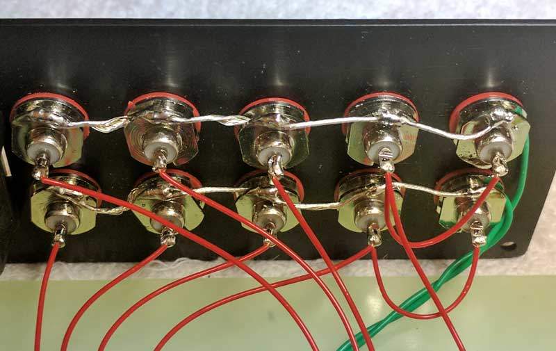
Each standard RCA jack has its own ground tab with a hole in it. You are going to run a ground wire through each of the 5 ground tab holes for the right channel jacks and a separate identical ground wire through the ground tab holes for the left channel. This is shown in the pic below.
Take 2 x 10 inch lengths of heavy green wire and strip 4 inches of insulation off of each leaving the other 6 inches insulated. While making sure you don’t unravel the stranded end, thread the bare wire through each of the 5 tabs. When done, solder each tab to its ground wire.
Before threading the wire through the ground tabs holes, make sure each tab is aligned with the next tab and using pliers twist each tab 90 degrees so the holes in the 5 tabs line up. This will make it much easier to thread the ground wire through the tabs holes.
Balanced version
The balanced kit differs from the single-ended kit as follows:
- The balanced kit uses a different rear panel with XLR type jacks where the pin 1 connections on both the input and output XLR jacks are wired together and terminated at the Star Ground point in a similar manner to the signal grounds for the single-ended RCA panel shown above.
Rear panel | single-ended wiring
Cut 9 x 4 inch lengths of signal wire from either the standard white stranded hookup wire or the optional solid Neotech wire.
Take 8 of these wires and strip roughly a 1/4-3/8″ of insulation off of one end only. Take the 9th wire and cut it in half into roughly 2 inch lengths and strip similar length of insulation off of both ends of both the shorter wires.
Starting with the bottom row (left channel) solder a single wire to each of the 3 left-most RCA jacks (the inputs) as viewed in the pic below. On the 4th RCA jack from the left (output jack 1 of 2) twist the ends of a 4 inch and a 2 inch length of wire together and solder that twisted pair end to the 4th jack. Then solder the other end of the short 2 inch wire to the 5th RCA jack from the left (output jack 2 of 2). Repeat this sequence for the top row of RCA jacks (the right channel).
At this point you are ready to proceed with connecting/soldering the rear panel wiring to the V25 board and the Star Ground. To proceed, place the rear panel along the edge of the end of the Mounting Board with the rear panel’s wiring facing towards you. We suggest you place something heavy like a dictionary behind the rear panel so that it stands up facing you as shown above.
The wiring of the audio signals between the RCA jacks and the V25 board is illustrated below for a single input and output. Follow the wiring termination schedule below for further details.
Rear Panel | balanced signal wiring
Balanced kits require two V25 boards with a data link connected between them and the audio inputs and outputs wired as described herein.
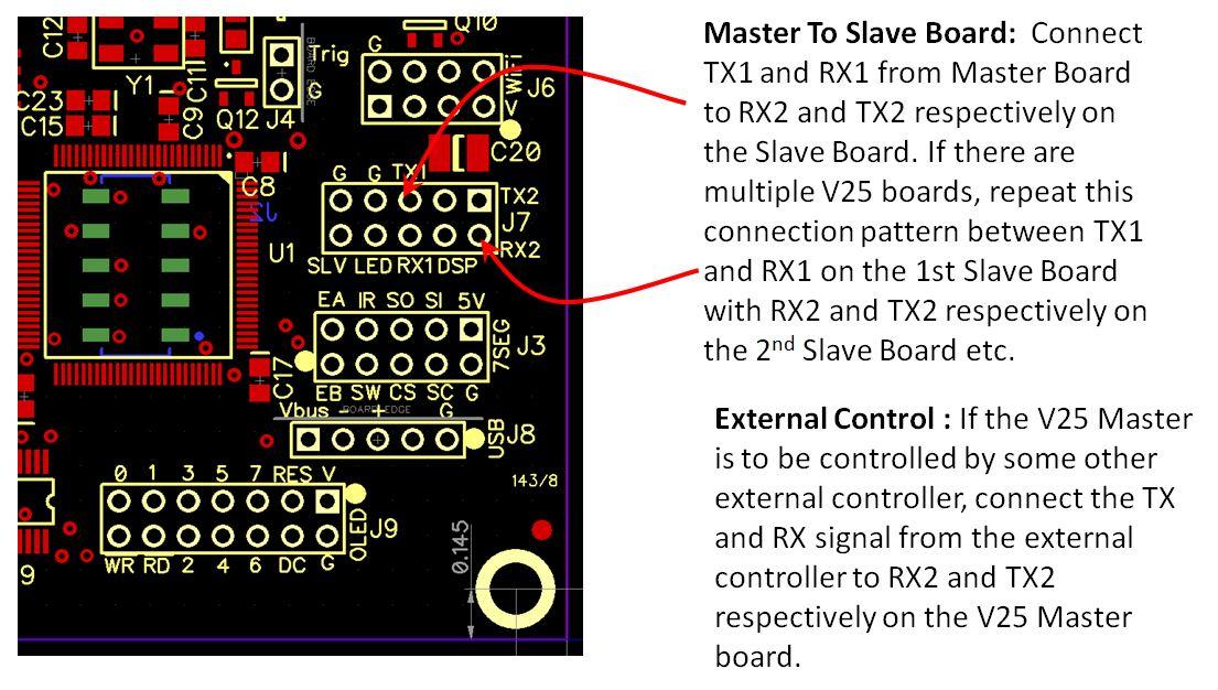
Data link
A 2-wire data link must connect the master/right V25 board to the slave/left V25 board. Pins J7:TX1/RX1 on the master board connect pins J7:TX2/RX2 on the slave board. The data link is how the 2 boards communicate with each other during blanced operation.
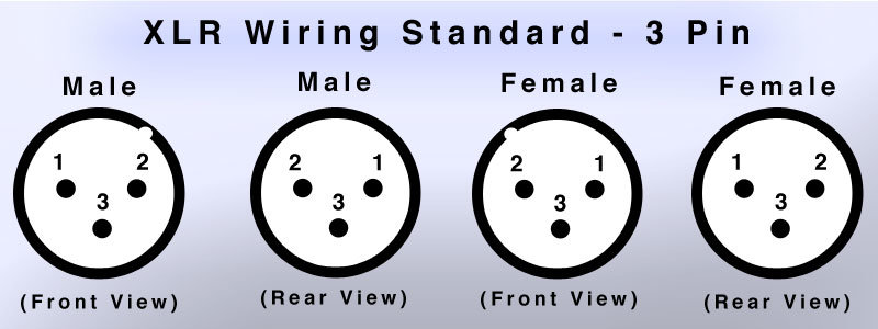
3-pin XLR wiring
Balanced XLR wiring is unavoidably more complex than single-ended RCA.
First, you are dealing with three (3) terminations per channel; two signals (pin 2 and pin 3) plus one shield/ground (pin 1). Next, you have both male (output) and female (input) type connectors each of which reverse the position of pins 1 and 2 with respect to the other while pin 3 remains thankfully unchanged. Last, but not least, some diagrams show the pins in a front view while another may use a rear view.
For purposes of your sanity and this guide, assume all XLR connectors herein are rear view only.
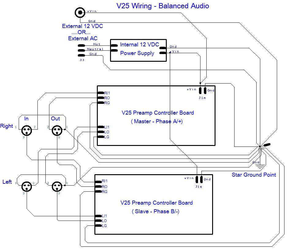
Balanced wiring | schematic
Connecting balanced audio signals and ground to the V25 can be challenging for the simple reason that it’s a bit complex and thus it’s easy to make a mistake.
The correct way to wire balanced audio to the V25 is shown below in two different diagrams. The first is a more abstract schematic representation while the second looks closer to actual wiring to the boards. In either diagram we only terminating a single input and a single output to the left and right channels.
Before diving in with wiring your V25 boards, we strongly recommend you study these diagrams until you understand the wiring scheme represented here. The wiring scheme is summarized in the following bullet points:
- Master board handles the A/+ phase of both the right and left channels
- Slave board handles the B/- phase of both the right and left channels
- All grounds (including the pin 1’s) get wired to a single common “star ground” point somewhere within the enclosure
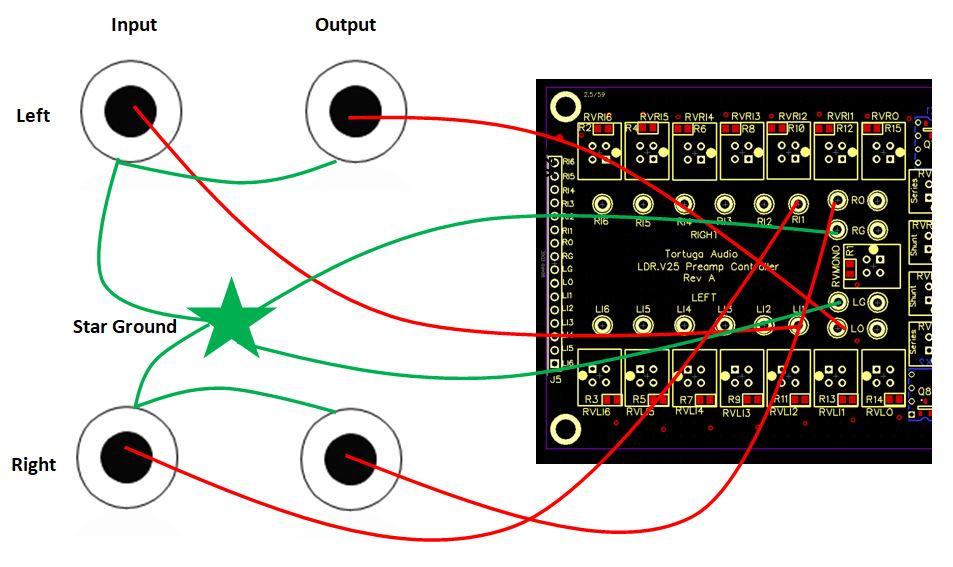
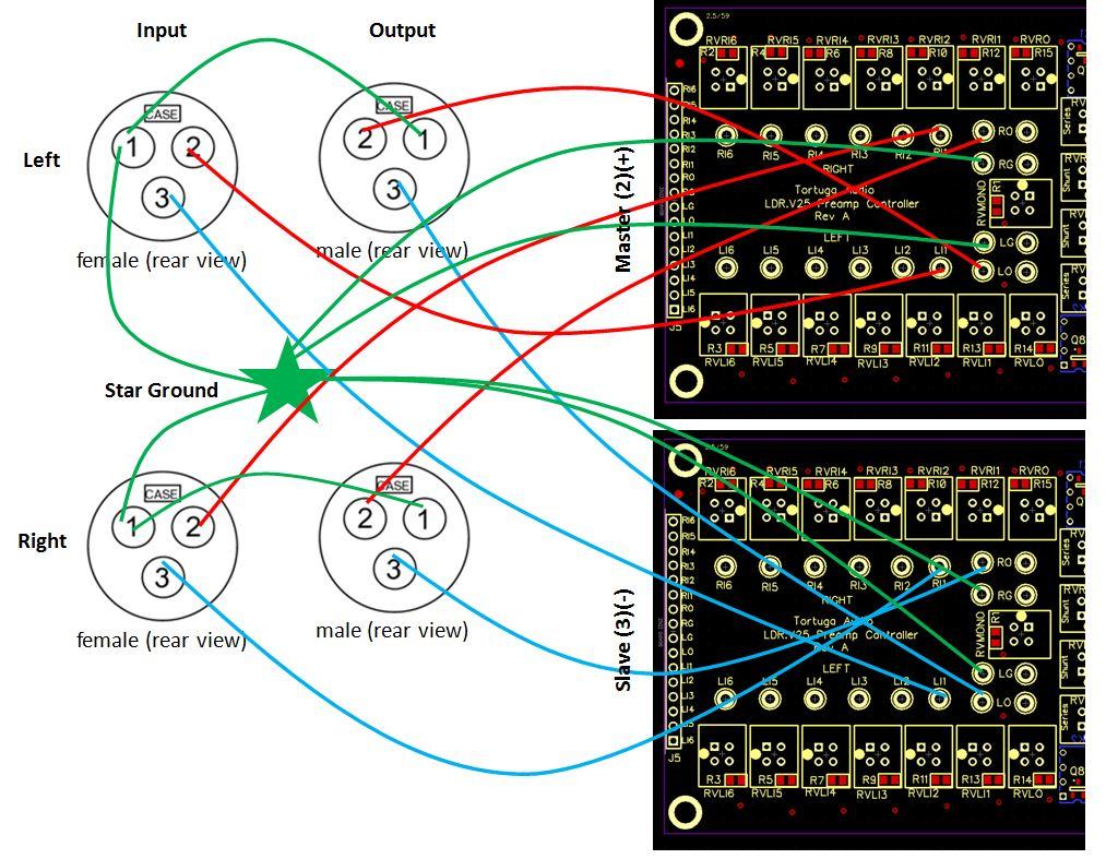
Balanced wiring | point to point connections
The wiring diagram shown below is consistent with the schematic shown above and is provided to show where the wires need to be connected on the actual V25 boards.
The master board (located on the right of the assembly) handles the + phase of the balanced signals and the slave board handles the – phase. Thus, the right+ channel terminates to the right channel of the master board and the right- channel terminates to the right channel of the slave board. Conversely, the left+ channel terminates to the left channel of the master board and the left- channel terminates to the left channel of the slave board. While a bit messy to follow, this is shown in the diagram below.
Rear panel | USB port
The V25 USB port is header J8. Although J8 is visible and labeled on the topside of the V25 board, early production V25 boards located the 5-pin header on the underside of the board as shown below. Latter production V25 boards moved the 5-pin USB J8 header to the top side of the V25 board. All information below is valid regardless of whether the J8 USB header is located on the bottom or top side of the V25 board.
The J8 USB port uses the standard 5 pin USB connections as follows:
- Vbus – the +5V line
- D-(minus) – the negative data signal
- D+(plus) – the positive data signal
- N/C – no connection
- G – ground
When connecting to the J8 USB port it’s extremely important to make sure that the Vbus/+5V line is connected to the #1 pin. Reversing the USB connection to the J8 port and then connecting a powered USB device will destroy the V25 board.
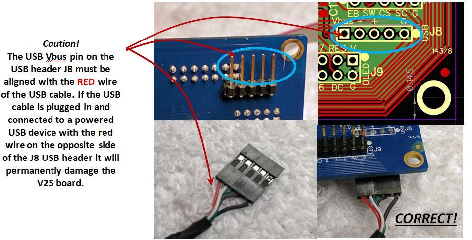
Please note that the USB port photo above shows the J8 port exiting the bottom of the V25 board. Early versions of the V25 board were made this way but later the pin header for J8 was installed on the top side of the board. The caution and connections are the same either way.
Wire/cable termination schedule
The following table lists each of the wires and cables and where each are to be connected either by soldering, plugging, crimping etc. You should have already partially or totally completed some of these already following the instructions above.
Please note that this wiring schedule has not been updated for the OLED display nor does it reflect wiring for the balanced version of the kit.
You are strongly encourage to refer to this schedule as a guide and checklist. One all of these connections have been made, you are all but done with your kit.
| Wire/Cable | From | To |
|---|---|---|
| Display Module Ribbon Cable #1 | Master (right) display module J3 (align red stripe with white dot on board) | Slave (left) display module J3. (align red stripe with white dot on board) |
| Display Module Ribbon Cable #2 | Master (right) display module J1 (align red stripe with white dot on board) | V25 board J3 (align red stripe with white dot on board) |
| Encoder Cable (4 conductor) | with DM1 Display Modules | Master (right) display module J2 (pins A, B, S & G) | Encoder module J1 (pins A, B, S & C) |
| Encoder Cable (4 conductor) | no Display Modules (direct from encoder to V25 board) | Encoder module J1 (pins A, B, S & C | V25 board J3 pins EA, EB, ES & G. |
| Power Jack | +12V Wire | 12 o'clock tab | heavy red wire | Crimp pin that goes into 0.156" 2 position latching socket so that when socket plugs into the V25 board's J1 power pins the red wire is on the outboard side (next to+Vin label) |
| Power Jack | Ground Wire | 3 o'clock tab | heavy black wire | Star Ground |
| V25 Board Ground Wire | Star Ground | heavy black wire | Crimp pin that goes into 0.156" 2 position latching socket so that when socket plugs into the V25 board's J1 power pins the black wire is on the inboard side (next to U4 label) |
| Trigger Jack | +12V Wire | 12 o'clock tab | light red wire | V25 board J4.Trig (solder) |
| Trigger Jack | Ground Wire | 6 o'clock tab | light red wire | Star Ground |
| Rear Panel | Left Channel RCA Signal Ground | Daisy chained bare wire through ground tab holes | heavy green wire | Star Ground |
| Rear Panel | Right Channel RCA Signal Ground | Daisy chained bare wire through ground tab holes | heavy green wire | Star Ground |
| V25 Board | Left Channel Signal Ground | V25 board LG solder pad | Star Ground |
| V25 Board | Right Channel Signal Ground | V25 board RG solder pad | Star Ground |
| Left Input #3 | Rear Panel left-most bottom RCA jack pin | medium stranded white wire or optional Neotech solid wire | V25 board LI3 solder pad |
| Left Input #2 | Rear Panel 2nd from left bottom RCA jack pin | medium stranded white wire or optional Neotech solid wire | V25 board LI2 solder pad |
| Left Input #1 | Rear Panel 3rd from left bottom RCA jack pin | medium stranded white wire or optional Neotech solid wire | V25 board LI1 solder pad |
| Left Output #1 | Rear Panel 4th from left bottom RCA jack pin | medium stranded white wire or optional Neotech solid wire (see Left Output #2 before proceeding) | V25 board LO solder pad |
| Left Output #2 | Rear Panel 4th from left bottom RCA jack pin | medium stranded white wire or optional Neotech solid wire (see Left Output #1 before proceeding) | Rear Panel 5th from left bottom RCA jack pin | medium stranded white wire or optional Neotech solid wire |
| Right Input #3 | Rear Panel left-most top RCA jack pin | medium stranded white wire or optional Neotech solid wire | V25 board RI3 solder pad |
| Right Input #2 | Rear Panel 2nd from left top RCA jack pin | medium stranded white wire or optional Neotech solid wire | V25 board RI2 solder pad |
| Right Input #1 | Rear Panel 3rd from left top RCA jack pin | medium stranded white wire or optional Neotech solid wire | V25 board RI1 solder pad |
| Right Output #1 | Rear Panel 4th from left top RCA jack pin | medium stranded white wire or optional Neotech solid wire (see Right Output #2 before proceeding) | V25 board RO solder pad |
| Right Output #2 | Rear Panel 4th from left top RCA jack pin | medium stranded white wire or optional Neotech solid wire (see Right Output #1 before proceeding) | Rear Panel 5th from left top RCA jack pin | medium stranded white wire or optional Neotech solid wire |
| USB Cable | Rear Panel | cable is molded to jack end which has been screwed into rear panel | Connect 5 pin female header end into the V25 board's J8 pin header located on underside of left front corner of V25 board. Make absolutely sure that the RED wire of the female header is aligned with rear most J8 pin (the pin labeled Vbus). |
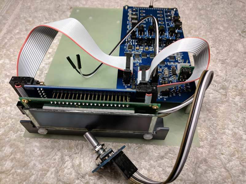
Finished assembly
If you’ve completed all the above steps including all the wire/cable terminations per the above schedule, your finished assembly should look something like the pic below.
You are almost done! The final steps include inserting the finished assembly into the enclosure box, attaching the encoder to the front panel, attaching both the front and rear panel to the enclosure box and attaching the knob to the encoder.
Install assembly into enclosure
The enclosure box has a series of internal slots on both the left and right inner walls. The left and right sides of the Mounting Board will slide into these slots. You need to use the bottom-most slot!
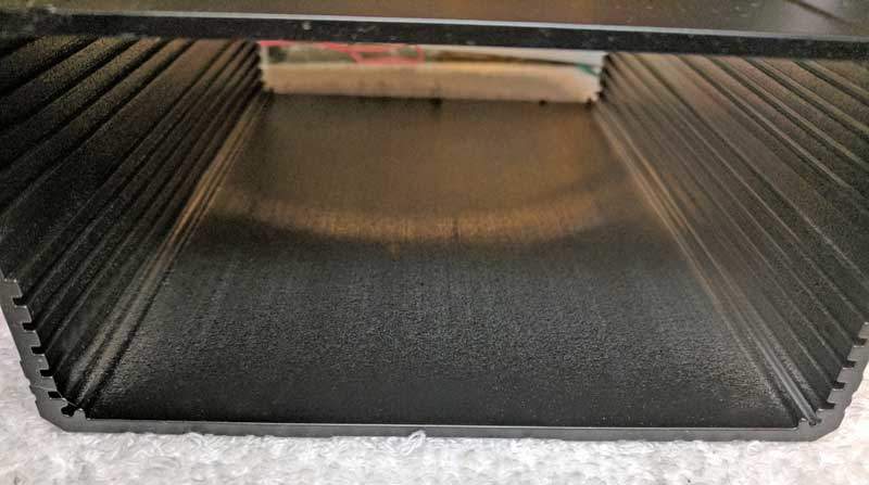
Slide the display end of the finished assembly into the enclosure box using the bottom most pair of slots. The pic below shows a finished assembly on the left and and a finished assembly fully inserted into the enclosure box on the right except for final attachment of the rear panel to the box.
Attach rear panel
Gently press the rear panel into the enclosure box. Install a black #4 socketed sheet metal screw with washer in each corner of the rear panel making sure you engage the extruded screw hole in each corner of the box. Since the screw holes in the enclosure box are not pre-tapped you will use the screws themselves to create threads in the enclosure the first time they are fully screwed into place. This will take a bit of extra torque on the hex wrench. Subsequent removal and replacement of these mounting screws will be much easier. Snug down the screws but do not over-tighten.
The rear panel area should now look like the pic below.
Attach front panel
Turn the unit around with the front facing you. Remove the nut and washer from the Encoder and insert it through the back side of the acrylic front panel. The rear side of the front panel will have a milled recess around the hole for the Encoder. Slip the washer and nut on to the encoder and tighten the nut gently yet firmly. At this point the front panel and preamp should look something like the pic below.
The last step in the assembly process is to attach the front panel to the enclosure box. Use the same black socket head screws and washers that you used for the rear panel. Do not over-tighten the screws.
If you haven’t already done so, the final step is to attach the knob to the Encoder shaft. The knob has a set screw that must be aligned with the flat part of the encoder shaft. Tighten the set screw firmly. After the set screw is secure check that when you press in the encoder that it doesn’t bottom out against the face of the front panel. If it does, loosen the set screw and pull the knob out “a smidge” and tighten the set screw again.
At this point the front panel area should look like the pic below.
And you are DONE!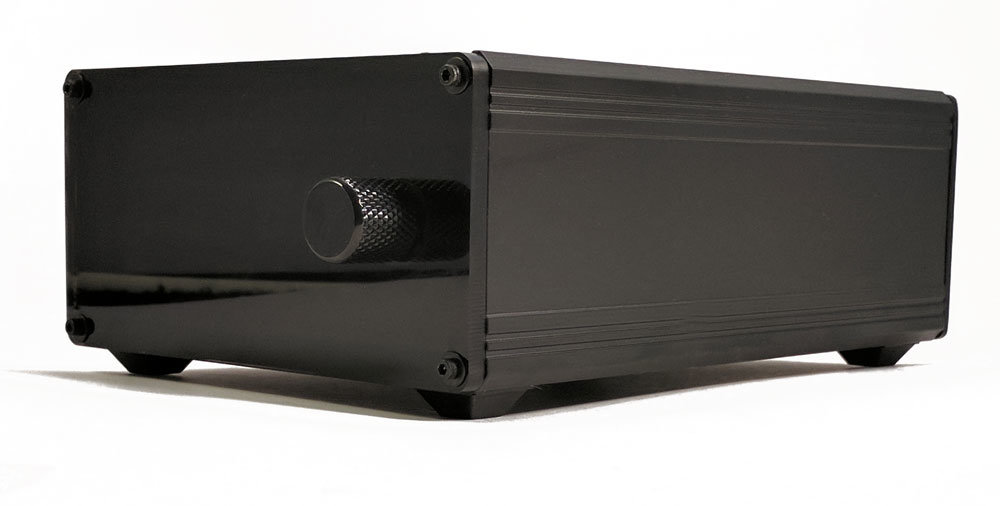
Troubleshooting
| Symptom | Suggestions |
|---|---|
| No response after applying power | * Each V25 was fully tested prior to shipping so lack of response to being powered up is unlikely to be due a problem with the board proper. * The V25 takes approximately 5 seconds to boot up after power is applied at which point it will briefly display a 4 digit firmware revision number and then turn off ready for normal use. * Double check that 12 volt power is present at the J1 power connector and that the +V is being applied to the J1 pin closests to the edge of the board. Reversing this polarity can damage the power regulaor. * Double check that wiring to the 12 volt power jack terminals is consistent with the instructions herein. * Double check that the ribbon cable connecting the master display module to the J3 10 pin header is connected and that the red stripe on the cable is aligned with the side of the header with the white dot on the board. |
| Unit turns on automatically after applying power | * The V25 takes approximately 5 seconds to boot up after power is applied at which point it will briefly display a 4 digit firmware revision number and then turn off ready for normal use. * If the unit turns on after the boot up and firmware version is displayed then the cause is most likely that the encoder is wired backwards and is sending the board a turn-on signal. Reverse the wires to the encoder and retry. |
| Righ display works but left display remains off | * Check that the ibbon cable is connected between the right and left display J3 headers. Confirm that the red stripe on the that ribbon cable is on on the top side at both ends. |
| Digits on 7 segment display are partially blank or corrupted | * First check the brighness level setting and make sure brightness is set down to 10 or less. * If problem persists after reducing brightness level, the problem is likely due to a bad ribbon cable between the board and the right display module or a bad ribbon cable betrween the right and left display modules. Replace as indicated. |
