Overview
Since inception, all Tortuga Audio preamp controllers and other preamp products have utilized a rotary encoder with integral push button as a means for manually controlling the preamp device. While limited in control functionality as compared to using an infrared remote control, the encoder has typically provided a means to control volume, power on/off, mute/unmute, channel balance, and even select between audio input sources.
Similarly, all Tortuga Audio preamp products have utilized infrared remote control requiring the presence of an infrared (“IR”) receiver module.
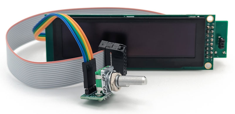
It has become our standard practice to make the encoder and the IR receiver an integral part of the OLED display assembly as shown below. While the OLED display assembly is mentioned herein, more information on the OLED display assembly can be found here.
Encoder module
An encoder is a type of rotary switch that generates a series of square wave pulses from two switches that are 90 degrees out of phase with respect to ground. This is referred to as quadrature encoding. The timing and sequence of these pulses vary depending on whether the encoder is being turned clockwise or counter-clockwise. The encoder Tortuga Audio uses also has a secondary push button function. Both the rotary pulses and the push button are monitored by a Tortuga Audio preamp controller which translates these signals into specific command sequences.

Unlike a typical volume control potentiometer, an encoder has no stops and thus can be turned any number of times. There are approximately 20 pulses generated per full rotation by the specific encoder used by Tortuga Audio.
For convenience, the encoder is mounted on small encoder adapter board equipped with a 4-pin male header. The encoder connects to the OLED display assembly via a 4-wire square pin connector cable to the OLED display adapter board as shown below in images below.
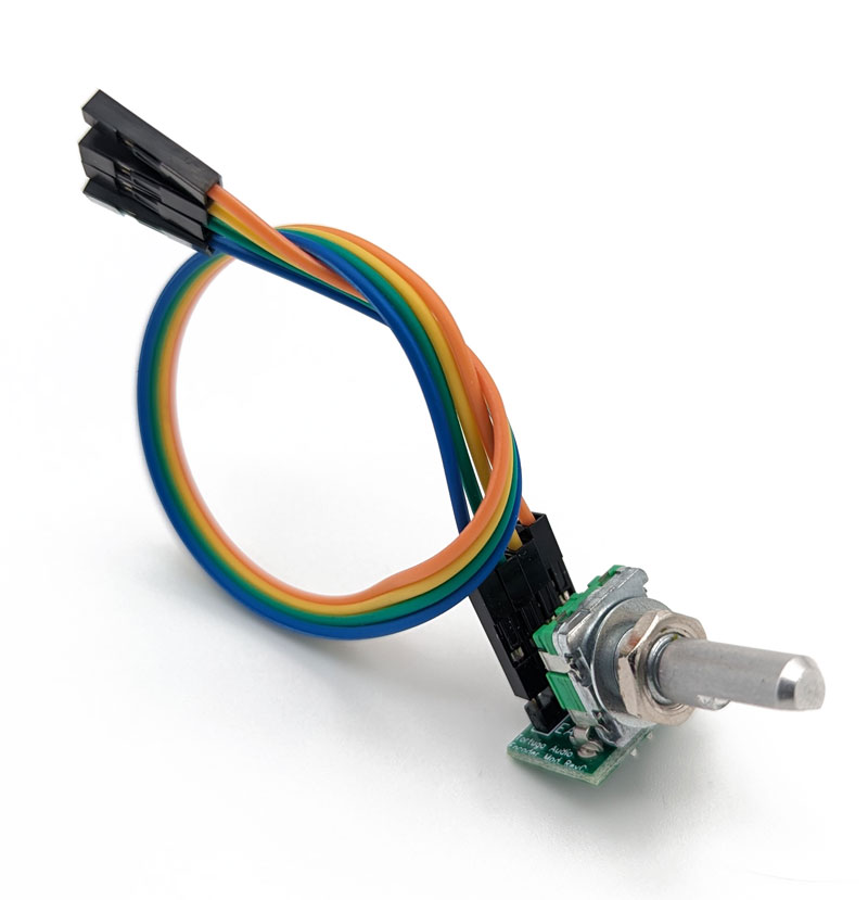
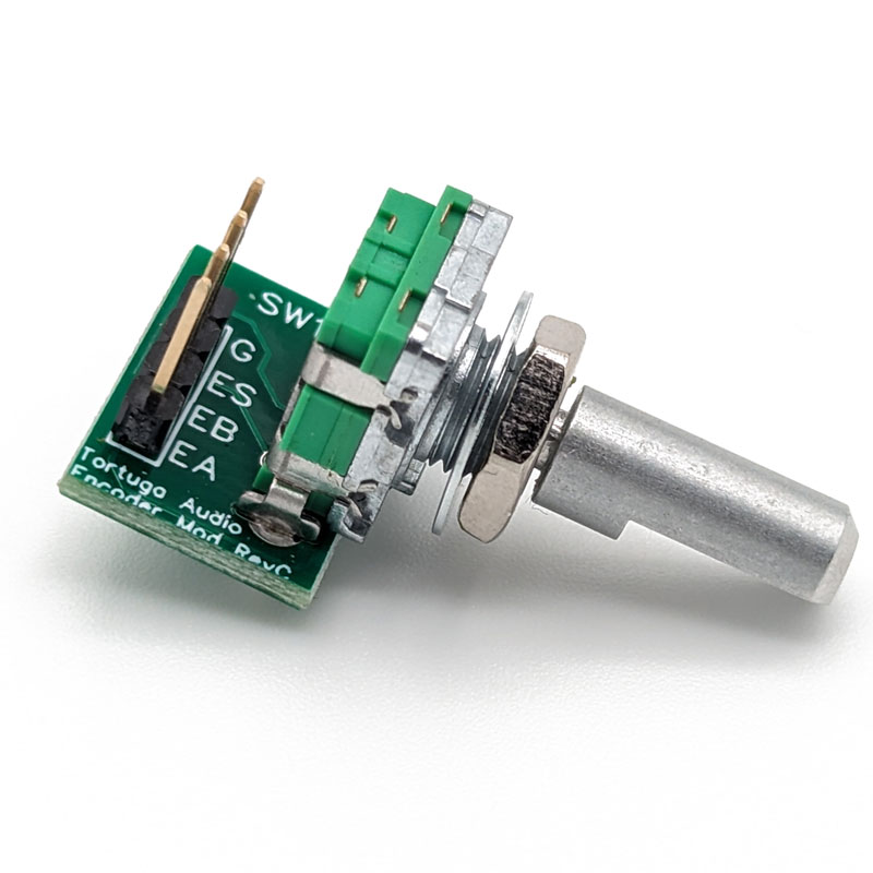
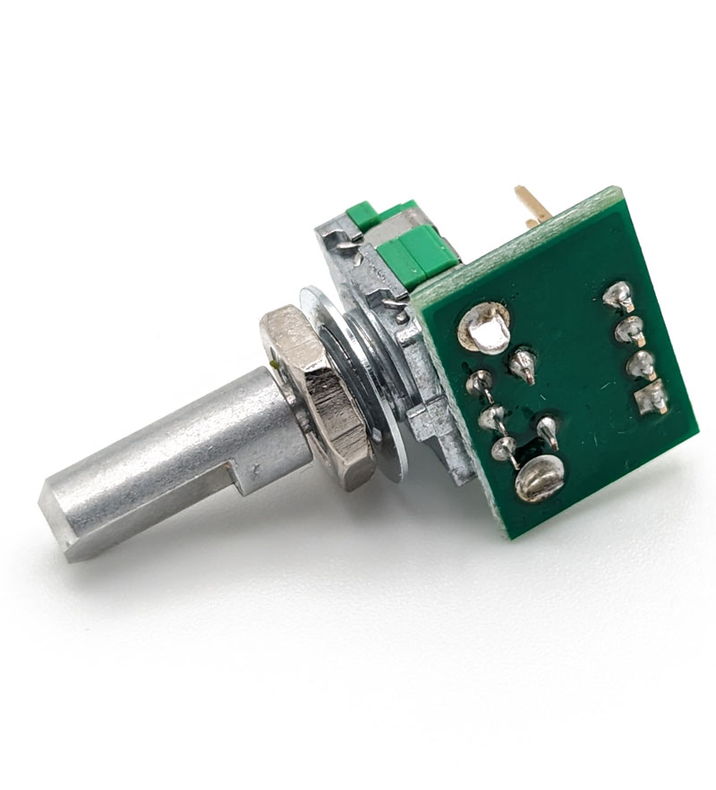
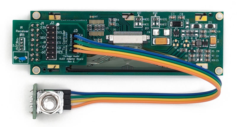
The J3 encoder header pin out is listed below.
- EA – encoder leg A
- EB – encoder leg B
- ES – encoder push button switch
- G – ground
Please note that if turning the encoder clockwise lowers rather than increases the volume, that you can simply swap the position of the EA (leg A) and EB (leg B) connections to correct this.
Infrared receiver module
The 4-wire infrared (“IR”) receiver module used in the current version of the OLED display assembly is soldered into the end of OLED adapter board where the adapter board extends slightly beyond the edge of the OLED display screen. This allows the IR receiver to “see” out into the listening room assuming the OLED display assembly is mounted into the front panel of a preamp and thus is itself facing out into the listening room.
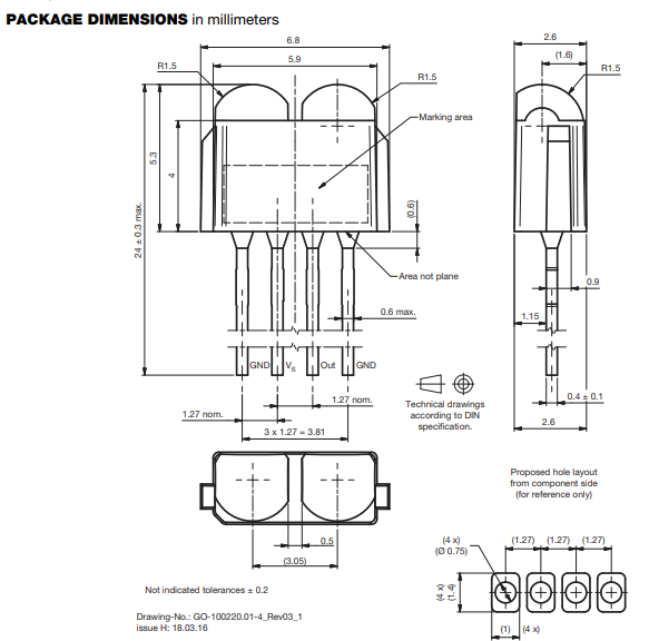
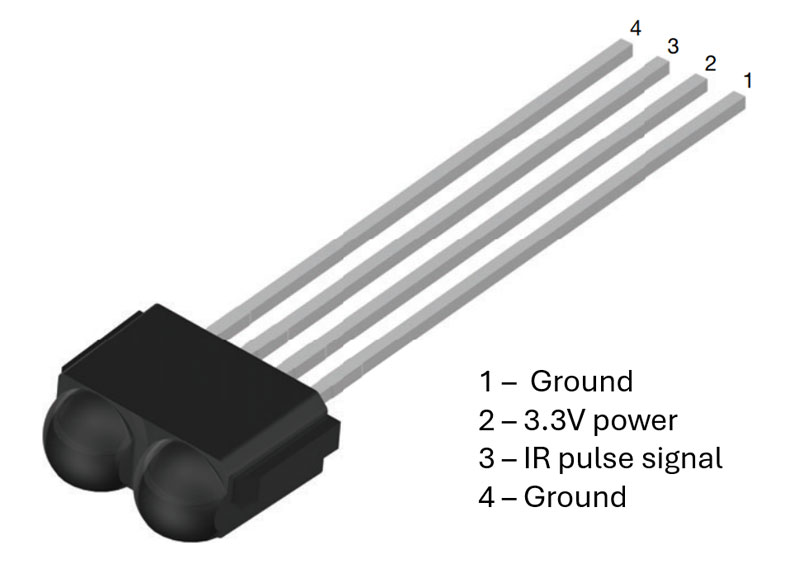
As with the encoder, the IR receiver has no connections into the OLED display screen itself. It sends its signal to an attached Tortuga Audio preamp controller board via the same 14-pin ribbon cable used by the encoder and the OLED display.
The IR receiver pin out is as follows:
- G – ground
- IR – received signal pulse
- 3.3V – power
- G – ground
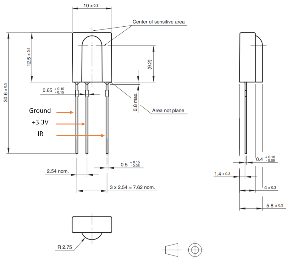
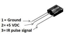
OLED display assemblies prior to June 2021 used a different 3-wire IR receiver module as shown below.
