Electronic Stepped Attenuator | ePot.V3 Max
$249.00
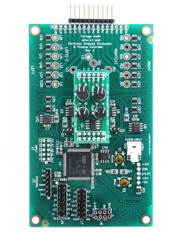
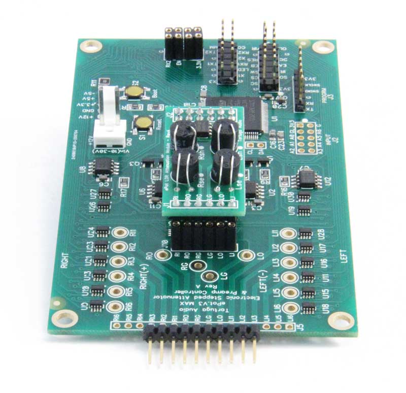
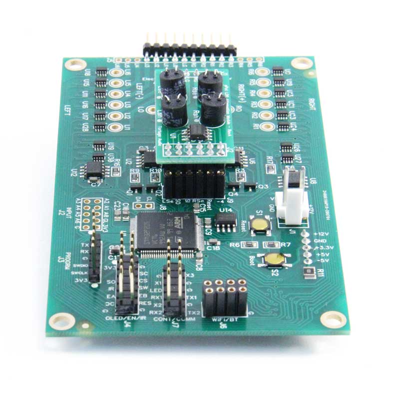
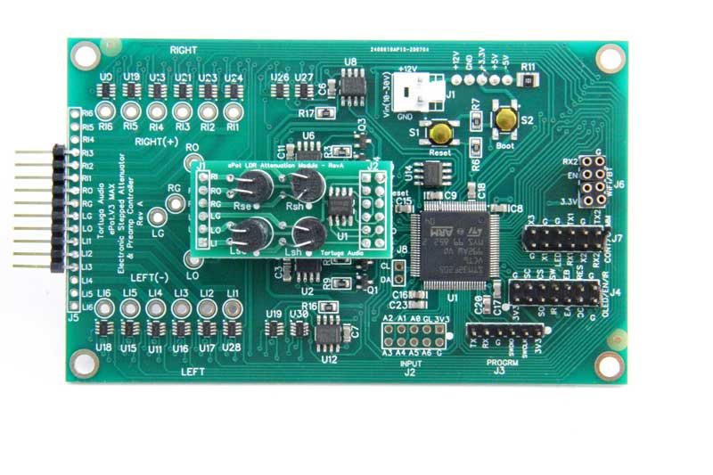
The ePot.V3 Max (the “V3 Max” or just “Max”) is a chassis mounted electronic stepped attenuator and preamp controller board for the DIYer, designer or OEM. The V3 Max provides 2-channel, 100 step stereo volume control, input switching for up to 6 sources, remote control, and optional (but highly recommended) high contrast OLED display with a menu driven interactive user interface. The V3 Max is an analog volume control device run by a software driven 32 bit ARM microcontroller. The audio signals are not manipulated in the digital domain. Analog audio signals passing through the V3 are optically isolated from any power source. There is no active gain stage and there is no active output/buffer stage. Each audio signal sees only 2 resistors (light dependent resistors – LDRs). The LDRs control volume by reducing the voltage of the incoming audio signal. By this definition the V3 is inherently a passive volume controller. By itself, the Max can be used as a passive preamp. When mated to a downstream gain and/or buffer stage the ePot.V3 Max becomes the attenuator/controller of a high performance active preamp. The Max is the successor product to Tortuga Audio’s popular LDR.V25 Preamp Controller. The V3 series represents Tortuga Audio’s 5th generation of of audio attenuation technology designed around light dependent resistors (LDRs).
Out of stock
V3 Max Rev C design update | October 2021 release
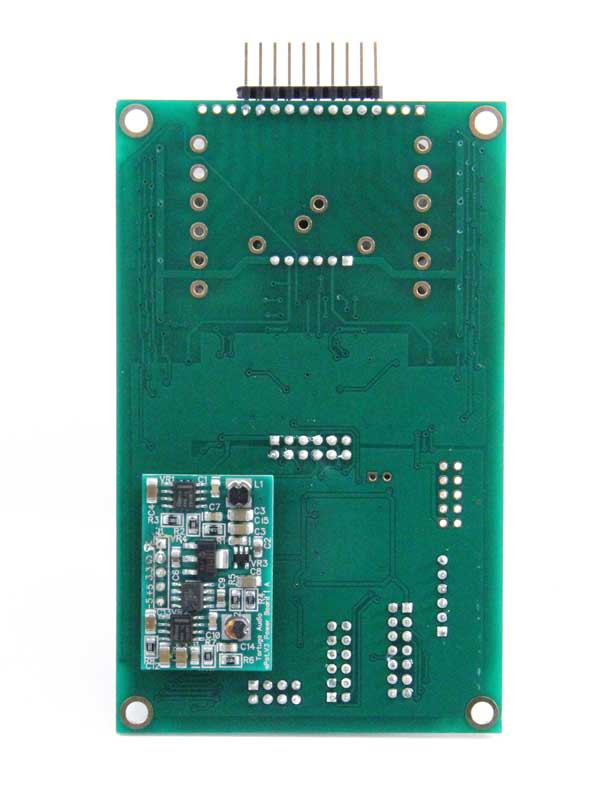
Ongoing development work has resulted in the Rev C release of the V3 Max electronic stepped attenuator. Rev C eliminates the separate attached piggy-back power board, with all components now on a single Rec C board. The result is more stable and robust product with even better sonic performance. The hardware revision changes are summarized in the table below.
| V3 Max Version | Rev A | Rev B | Rev C |
|---|---|---|---|
| Release Date | Sept 2020 | May 2021 | 1Q2022 |
| DC-DC power board | Based on a design by Texas Instruments | Simpler, more robust, more efficient, quieter design by Tortuga Audio | Same design as Rev B but power board eliminated and parts moved on to main board. |
| Minimum load resistor | Negative 5 volt minimum load resistor for stability | Deleted, no longer required. | same as Rev B |
| 3.3 volt power capacitor | Small – ceramic. | Added larger electrolytic storage capacitor to ensure stable supply during any transients | same as Rev B |
| Mono mode | Yes | No – removed the mono mode switch to eliminate any possibility of channel cross talk during normal operation | same as Rev B |
| Part Changes | Baseline | Removed: U31 & R11 Relocated: S1, S2, R6 & R7 Added: C13 Replaced: Power board (located on underside of main board) | Deleted the S1/S2 boot/reset switches |
An electronic stepped attenuator | preamp controller
The ePot.V3 Max (the “V3 Max” or just “Max”) is a chassis mounted electronic stepped attenuator and preamp controller board for the DIYer, designer or OEM.
The V3 Max provides 2-channel, 100 step stereo volume control, input switching for up to 6 sources, remote control, and optional (but highly recommended) high contrast OLED display with a menu driven interactive user interface.
The V3 Max is an analog volume control device run by a software driven 32 bit ARM microcontroller. The audio signals are not manipulated in the digital domain. Analog audio signals passing through the V3 are optically isolated from any power source. There is no active gain stage and there is no active output/buffer stage. Each audio signal sees only 2 resistors (light dependent resistors – LDRs). The LDRs control volume by reducing the voltage of the incoming audio signal. By this definition the V3 is inherently a passive volume controller.
By itself, the Max can be used as a passive preamp. When mated to a downstream gain and/or buffer stage the ePot.V3 Max becomes the attenuator/controller of a high performance active preamp.
The Max is the successor product to Tortuga Audio’s popular LDR.V25 Preamp Controller. The V3 series represents Tortuga Audio’s 5th generation of of audio attenuation technology designed around light dependent resistors (LDRs).
Features of the ePot.V3 Max include:
- LDR (light dependent resistor) attenuation module
- 100 step attenuator
- -60 to 0 dB
- adjustable impedance from 1k to 100k (20k by default)
- integrated LDR calibration (no LDR matching required)
- plug-in replaceable attenuation module
- Input switching between 6 stereo sources
- Smooth stepping with no sonic artifacts
- No mechanical switches in the signal path
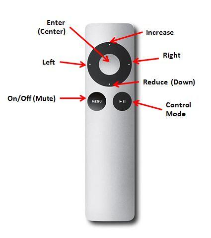
- Remote controlled (Apple infrared remote)
- Manual control via rotary encoder with integral push button
- Smooth muting/unmuting
- Left/right channel balance w/ reset (+/- 10 db)
- Optional status LED
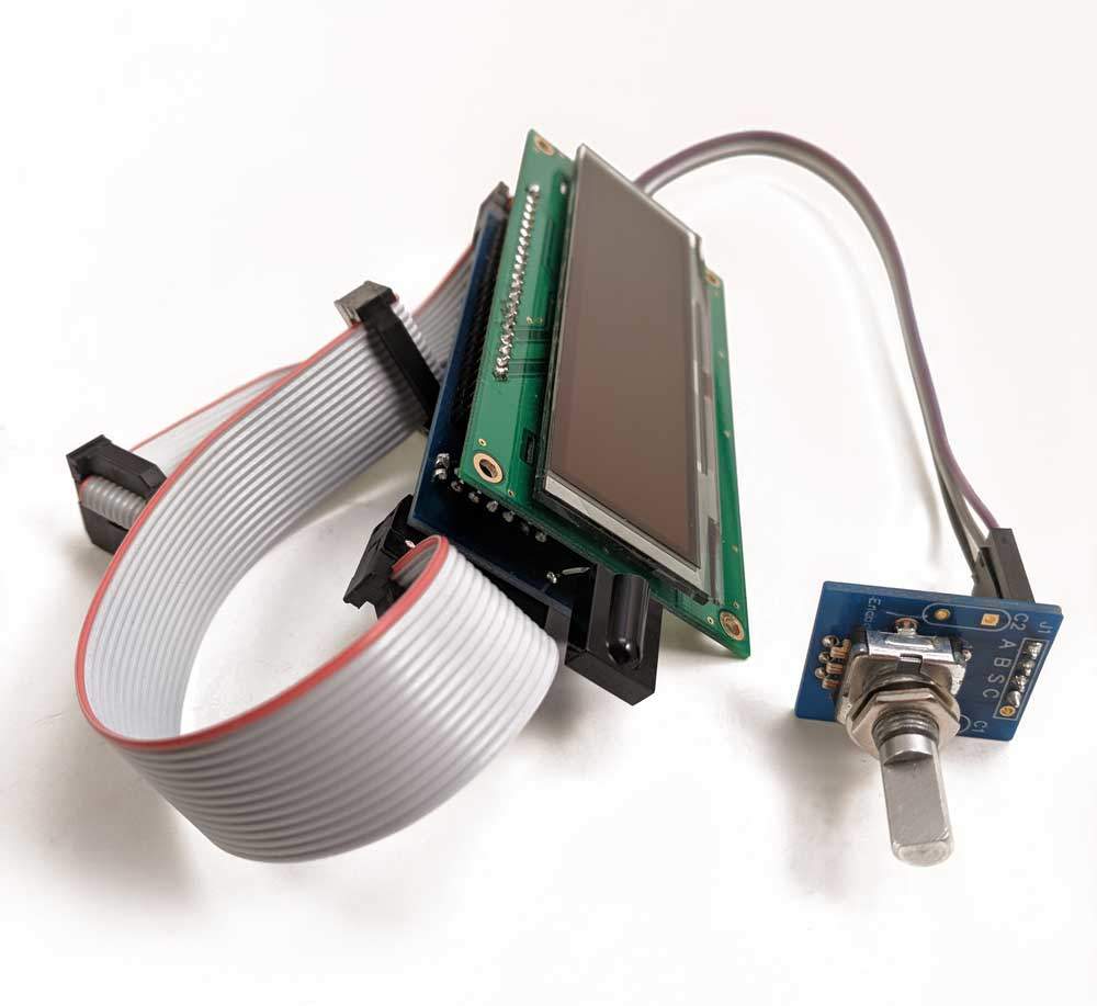
- Optional high contrast 256×64 pixel menu driven OLED display with encoder & IR receiver
- Compact – 2.9″ wide x 4.4″ long x 1.2″ deep
- Chassis mounted with standoffs
- Serial (UART) and TTL communication & control interfaces for customization
- 100 MHz ARM microcontroller programmed in object oriented C++ programming language
Hardware description
A detailed description of the V3 Max board is available here in our online production documentation (“Docs”).
Operation & control
A detailed description of the V3 Max board operation and control is available here in our online product documentation (“Docs”.
What’s included?
The following items are included by default with each Max.
- ePot.V3 Max board with attached triple voltage power supply board
- IR receiver module with 6 inch 3-wire square pin connector cable
- Status LED with 6 inch 2-wire square pin connector cable
- Power connector plug with crimp pins
You can opt to purchase the Max board “bare” without any attenuation module at a reduced cost provided you already have an existing LDR or discrete attenuation module. To be clear, an attenuation module is absolutely needed for the Max to function.
Optional items
The following are classified as “optional” but with strong recommendation as noted.
- Optional – OLED display assembly: (highly recommended) The V3 Max is engineered to work optimally along with this visual display. Includes IR receiver, encoder and cables.
- Optional – Encoder: (highly recommended) For manual control and for pairing the Apple remote. Is included as part of OLED display.
- Optional – Apple remote: (highly recommended) Required for remote control
What’s not included?
You will have to supply the following items:
- Nominal 12 VDC power supply. The V3 can be powered from any DC voltage from 9 to 30 VDC and draws no more than 0.3 A of current (with OLED display).
- The optional items listed above
- Audio signal input/output jacks
- Preamp enclosure
What do you have to do?
The key steps to getting the Max fully functional include the following:
- Mount it into a chassis
- Connect it to a DC power source via the power plug
- Connect the left and right channel signal inputs, outputs and grounds via either solder pads or pin header
- Connect some combination of the OLED display, Status LED, IR Receiver and/or Encoder to the V3 board either directly or indirectly
LDR attenuation module
Like its predecessors, the ePot.V3 offers high performance attenuation using light dependent resistors (LDRs). LDRs offer a very pleasing clean, clear, unveiled, neutral, colorless, yet natural organic sounding volume control with remarkable bass performance. The reader is referred to the following link for a more in depth discussion about LDRs.
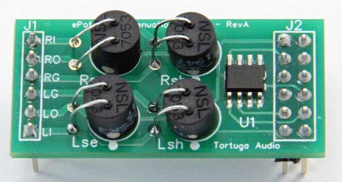
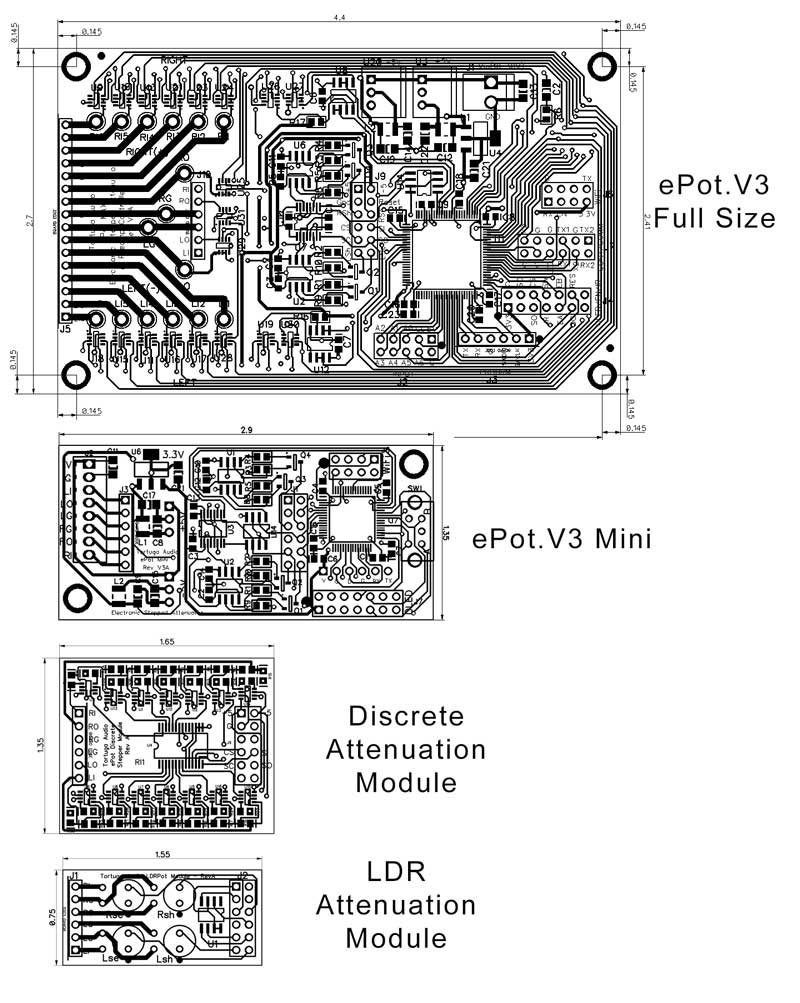
The V3 LDR Attenuation Module is a new LDR module design where all 4 LDRs are now mounted together on a single board along with an EEPROM memory chip that holds the impedance and attenuation setting data that are unique to each set of LDRs. The LDR Attenuation Modules plugs directly into either ePot.V3 model.
The LDR Attenuation Module provides 100 attenuation steps of ~ 0.6 dB/step over a -60 to 0 dB attenuation range. While we call them attenuation “steps” the transitions between steps are smoothly continuous since LDRs are themselves true analog devices. There are no audible stepping artifacts and the control is smooth and precise over the full range.
About LDR impedance and calibration
Due to its small size, the Mini is not capable of calibrating its own LDR attenuation module. Therefore is you need an LDR attenuation module with a difference impedance level or to replace a bad module you will need to purchase LDR modules from Tortuga Audio. Alternatively, if you also own an ePot.V3 Max you can use any Max to recalibrate any LDR module at whatever impedance level you wish. If you send in your existing V3 LDR attenuation module, we will recalibrate your module for you for a $5 fee plus return shipping.
For more general information, please refer to this link to read more about LDRs, their impedance and their calibration.
Improved LDR control & calibration
The ePot.V3 introduces a significantly improved LDR control scheme compared to all prior models.
The light source inside a “light” dependent resistor is actually an LED. As with any LED, the light intensity emitted by the LED is directly proportional to the current running through it. And by controlling light intensity you control the resistance level of the LDR. Hence, precise current control is synonymous with precise resistance control. In the past we’ve accomplished this indirectly with voltage control.
With the V3 we have replaced voltage control with precision closed loop LDR current control. Precision current control decouples LDR performance from power supply voltage levels resulting in more predictable, stable and repeatable LDR performance over a wide range of current.
In addition to precision current control, the ePot.V3 also has an improved LDR calibration system that replaces the previous 12 bit system with a simpler yet more precise 16 bit approach. LDR calibration is a built-in feature of the ePot.V3 Max. The reader is referred to the following link for a more in depth discussion of LDR calibration.
As a result, the sonic performance of the ePot.V3 running with LDR attenuation is now at the highest levels we’ve achieved to date.
Visual feedback & display options
The ePot.V3 will operate without the need for any visual feedback. Basic status feedback is available through the optional attachment of a single status LED which indicates on/off status and briefly flashes acknowledging a control input from the remote.
Full control functionality and visual feedback requires our graphical OLED display and an Apple remote together with the Mini’s built-in encoder.
The following table summaries the key differences in control capabilities between the status LED light and the OLED Display options.
| No OLED Display ePot.V3 Max | No OLED Display ePot.V3 Mini | With OLED Display ePot.V3 Max | With OLED Display ePot.V3 Mini |
|
|---|---|---|---|---|
| Power On | 1) Remote menu button toggle 2) Encoder press/release | Same | Same | Same |
| Power Off | 1) Remote menu button toggle 2) Encoder press/hold(5 sec)/release | Same | 1) Off Menu 2) Encoder press/hold/(5 sec)/release | Same |
| Volume Change | 1) Remote raise/lower buttons 2) Encoder turn right/left | Same | Same | same |
| Input Change | Encoder press/hold/turn | N/A | 1) Input Menu 2) Encoder press/hold/turn | N/A |
| Mute Toggle | 1) Remote mute button toggle 2) Encoder press/release | Same | Same | same |
| Channel Balance | Remote left/right buttons (Press/hold remote center button 5 secs to reset) | Same | Balance Menu Same | Same |
| LDR Calibration | No | N/A | Calibration Menu | N/A |
| Display Brightness | N/A | N/A | Display Menu | Same |
| Display Timeout | N/A | N/A | Display Menu | Same |
| Max Volume Upon Change | No | Same | Max Vol Menu | Same |
| # Inputs | No | N/A | #Inputs Menu | N/A |
| Reset | No | Same | Reset Menu | N/A |
| Menu Options | No | Same | Options Menu | Same |
| Version Info | No | Same | Version Menu | Same |
ePot.V3 specifications
The following table is a fairly comprehensive listing of the specifications of the V3 hardware. A detailed description of the hardware including its operation & control can be found in in our online production documentation for the V3 controller.
| Criteria | |
|---|---|
| Attenuator/preamp type | Passive electronic stepped attenuator & preamp controller. There is no active manipulation of the audio signal by any power supply. The audio signal is optically isolated from the control system. |
| Attenuation module | Operates interchangeably with either a plug-in LDR (light dependent resistor) Attenuation Module or a plug-in Discrete Resistor Attenuation Module * LDR Attenuation Module – 100 0.6 dB steps over a 0 to 60 dB range plus 1 additional muting step. A microcontroller uses 100 stored calibration/attenuation command values for each of the 4 attenuation LDRs for a given input impedance and sends commands for the current volume step to a 4 channel 16 bit DAC that in turn drives 4 independent precision closed loop LDR current controllers. * Discrete Attenuation Module – 127 0.5 dB steps over a 0 to -63.5 dB range plus 1 additional muting step. Selects up to 7 series/shunt pairs of logarithmically arranged discrete resistors per channel to achieve 127 steps of attenuation over a 0 to -63.5 dB range at a fixed 60k input impedance. |
| Gain | Unity (1x) gain – no amplification |
| Buffering | No active or passive input or output stage buffering or coupling |
| Input impedance | * LDR Attenuation Module – 20k by default | may configure up to 9 additional impedance settings each adjustable between 1k and 99k and switch between the settings with live music to optimize input impedance for their system. * Discrete Attenuation Module – 60k fixed |
| LDR Calibration | * ePot.V3 Max – Integrated offline LDR module measurement and calibration against 100 attenuation resistance values that vary depending on the current input impedance setting with results stored in an EEPROM memory located on the plug-in LDR module. Calibration is an offline operation and does not occur during normal operation of the attenuator. Calibration is user initiated by can also be configured for periodic automatic operation when unit is otherwise turned off. Changing an input impedance to a new value within a given setting requires running a calibration cycle at that new value. * ePot.V3 Mini – no built-in LDR calibration |
| Number of Channels | 2 independent channels (stereo) |
| Channel Balance Accuracy | Within 0.5 db over full attenuation range |
| Audio Signal Ground | No connection of signal grounds to power ground within controller, however, audio signal ground must share common ground with power supply via an external star ground point in order for LDR self-calibration feature to function properly. |
| Audio Inputs | Single Ended | ePot.V3 Max – 1 board accommodates up to 6 switchable single-ended stereo (2 channel) inputs ePot.V3 Mini – 1 stereo input only (no input switching) |
| Audio Inputs | Balanced | ePot.V3 Max – 2 boards accommodate up to 6 switchable balanced stereo (2 channel) inputs. With 2 boards it’s possible to configure a mix of single-ended and balanced inputs. ePot.V3 Mini – not for balanced audio |
| Audio Input Switching/Isolation | ePot.V3 Max – Input switching via analog switches | typical 2 ohm resistance when on | in excess of 10 megaohms when off | no mechanical relays in signal path. ePot.V3 Mini – no input switching |
| Audio Output Switching/Isolation | ePot.V3 Max – Attenuation LDRs minimize output during muting | Analog switches isolate output signals when undergoing calibration ePot.V3 Mini – No output isolation |
| Total Harmonic Distortion | LDR Attenuation Module – typically less than 0.5% Discrete Attenuation Module – typically less than 0.1% |
| Power Input | 7-30 volts DC rated at 0.5 amp via J1 |
| Power Regulation | Two stage DC-DC regulation | switching regulation followed by linear regulation for 3.3V digital power and split voltage +/-4.5-5 V for analog power |
| Processor | ARM STM32F2 32 bit microcontroller running at 100 MHz |
| Control Input | Remote | Accepts control inputs from infrared silver Apple remote or equivalent remote using 38 kHz NEC protocol and Apple commands | infrared commands received via infrared receiver module attached indirectly via display module or directly to board pins |
| Control Input | Encoder | Accepts control inputs from rotary stepped encoder with integral push button switch | encoder attached indirectly via display or can be attached directly to board pins |
| Control Input | UART | Accepts control inputs from external device using UART serial protocol and specific command codes (available upon request). |
| Display | OLED | Graphic OLED display with an intuitive, easy to use, menu based control scheme. Connects to the board via both J4 header. Requires display jumper across pins at J7.DISP pins. |
| Display | 7-Segment (legacy) | Original dual 2-digit numerical 7-segment LED display can be connected via individual J4 pins although overall functionality is not guaranteed. |
| Display | Status LED | Status LED light | connects to board via J7 |
| Mono Mode | ePot.V3 Max | Rev A – Output switchable between stereo and mono mode via LDR switch | applies on to single-ended audio ePot.V3 Max | Rev B – No mono mode ePot.V3 Mini – No mono mode |
| Firmware | Custom code written in object oriented C++ programming language |
| Firmware Update | Firmware can be updated by invoking a chip resident bootloader that communicates with an extern PC based application. Firmware interface from PC to ePot is via a USB->Serial (FTDI USB->UART) com connection. FTDI communication interface sold separately. |
| WiFi Module | Future ability to plug in a simple WiFi module via J6 that will allow the V3 to be controlled via smartphone app. |
| Printed Circuit Board | High quality nickel immersion gold pads with green solder mask |
| Power | ** Current Draw ** Single board w/ OLED display – 130 ma Dual boards (balanced or dual mono) w/ single OLED display – 210 ma ** Supply Voltage ** 9-30 volts DC |
