
Operation overview
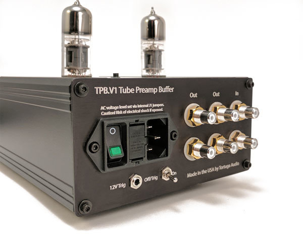
The TPB.V1 Tube Preamp Buffer (the “Buffer”) is simple to operate insofar as it’s either turned on or turned off and there are no other controls involved aside from the optional ability to control turn on/off via an external 12 volt trigger input. Operation is the same for either the single-ended version (shown in pic below) or the balanced version.
Front panel
The front panel (not shown here) has a single blue LED status light located in the center of the panel. When the buffer is going through its 10 second warm up cycle the LED will blink. When the warm up cycle is completed and the buffer is unmuted the LED light will remain on.
Rear panel
The rear panel has the following elements.
| Panel Element | Description |
|---|---|
| Power Entry Module | A standard IEC power entry module with integral fuse drawer and master power switch with indicator light |
| Input Jacks | A single set of input jacks for both singled ended model (RCA) and balanced (XLR) |
| Output Jacks | A dual set of output jacks are available for both single ended and balanced models. These dual outputs are wired in parallel. They are not separate output channels. |
| On/Off-Trigger Toggle Switch | Turns the buffer on/off manually. When in the off position, the buffer can be turned on/off remotely via a 12 V trigger input. |
| Trigger Jack | Accepts an external 12 V signal that turns the buffer on/off when the trigger toggle switch is in the Off-Trigger position. |
Power On/Off Sequence
When turned on (either manually or via external trigger) the buffer goes through the following power on sequence:
- Output remains muted (connected to ground)
- Tube heaters are turned on and a timer is started
- After 10 seconds the plate voltage is turned on
- After an additional 2 seconds the output is unmuted and the buffer is now fully on and operational
When turned off the output is immediately muted followed by both the tube heater and plate power being turned off.
Manual On/Off switching
To turn on the buffer manually make sure the silver toggle switch on the rear panel is set to the ON position and then flip the power entry rocker switch located on the rear panel to the on position by pressing the green lens side of rocker switch in. The green light on the rocker switch should light up. This will initiate the Power On Sequence described above.
External “trigger” control
The buffer is equipped with a 12 volt trigger input jack. When configured correctly, this trigger input allows the buffer to be turned on by any remote device that generates a nominal 12 volt signal.
To turn the buffer on remotely, make sure the silver toggle switch on the rear panel is set to the OFF/TRIGGER position and then flip the power entry rocker switch located on the rear panel to the on position by pressing the green lens side of rocker switch in. The green light on the rocker switch should light up. The presence of nominal 12 volts on the trigger input will initiate the Power On Sequence described above. When the trigger input voltage is removed or unplugged the buffer will turn off automatically.
With external trigger control you should leave the main power entry rocker switch turned on.
