
Overview
This manual provides a basic overview of the hardware and operation of the LDR3000T tube preamplifier. Because the LDR3000T preamp is built around the V25 preamp controller, detailed operating instructions are available in the online documentation on the V25 controller.
Enclosure box
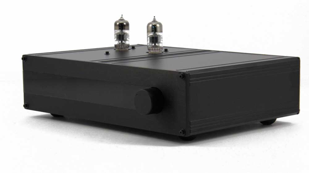
The enclosure shown in the photo above is composed of 2 identical heavy walled, black powder coated, extruded aluminum boxes bonded together. The internal assembly shown in the photo below slides into the enclosure box via the rear and includes the rear panel itself which attaches to the rear of the enclosure box. The front panel assembly is separate from the internal assembly and attaches to the front of the enclosure box. A toroidal power transformer (not shown) is through bolted to the bottom of the left front corner of the enclosure box.
Toroidal transformer
A 50 VA toroidal transformer is through bolted to the bottom of the front left corner of enclosure box. It sits immediately under the front left corner of the tube board and immediately behind the left front of the front panel. The transformer is not shown in any of the photos here.
Front panel assembly
The front panel assembly is made up of a 0.25 inch thick brushed anodized aluminum panel with a dark acrylic lens inlay, a rotary encoder with integral push button and control knob, and an OLED display assembly (not shown here) which is bonded to the back side of the front panel and sits directly behind the center of the acrylic lens. The front panel attaches to the front of the enclosure box via 4 socket head screws.
Internal assembly
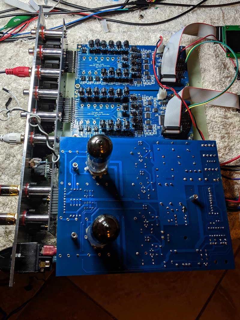
The internal assembly is composed of 3 components and sub-assemblies as shown in the photo below. The entire internal assembly slides into the enclosure box with the tube board going into the left side box and the controller boards going into the right side box. Each of these 3 are discussed briefly below.
Rear assembly
The rear assembly is shown in the left side of the photo above. It includes the rear panel itself, the RCA/XLR input/output jacks, USB port module (firmware updating), trigger out jack, and IEC power entry, and interface circuit board. The vertical interface circuit board is bonded to the rear panel via the XLR and RCA jacks. The tube board and the V25 controller boards connect to the interface board via pin headers.
Tube board
The tube board is the large circuit board with 2 tubes shown in the foreground of the photo above. It includes the power supply, tube input/gain stage, and the JFET output stage including the output coupling capacitors. The tube board plugs into the Rear Assembly via a pin header. After the tube board has been inserted into the enclosure box, the tube board is secured via 3 socket head screws/standoffs to the top of the enclosure box.
Controller/attenuator boards
There are two V25 controller/attenuator boards as shown side by side in the center/upper part of the photo above. The center V25 board is the main controller board and handles the right channel. It also handles user inputs via the remote and encoder and drives the OLED display. The upper V25 board handles the left channel and is slaved to the main board. The V25 boards plug into the rear assembly via pin headers.The 2 V25 boards are mounted on a board which slides into the bottom slot of the enclosure box. The front panel’s OLED display attaches to the center V25 board via a single 14 pin ribbon cable.
Operations | rear panel
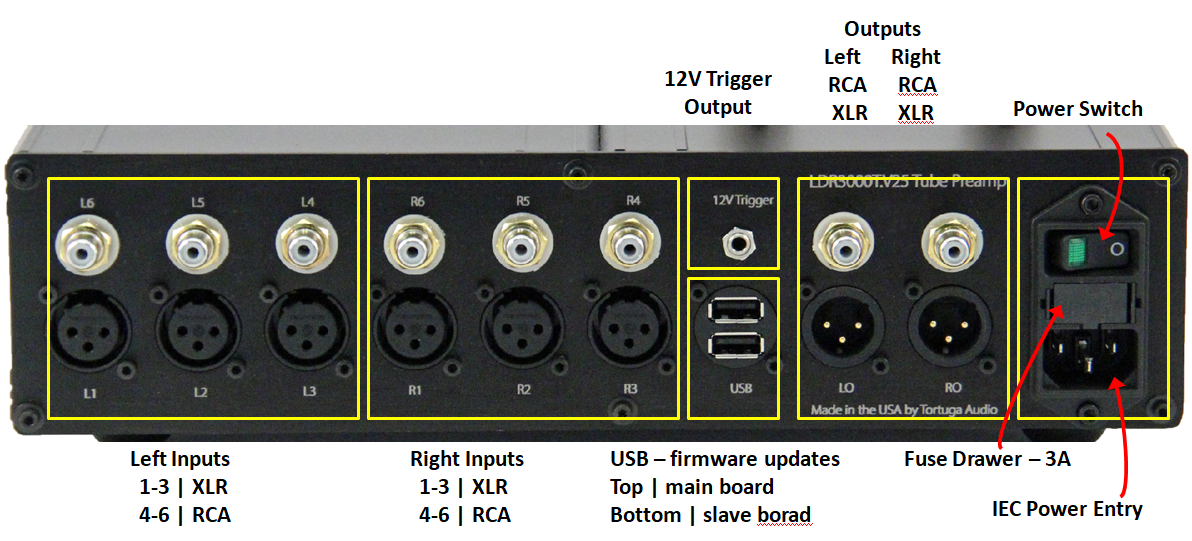
The LDR3000T rear panel is shown in the photo below with superimposed highlighted areas and annotations. The following information summarizes each highlighted area.
Inputs
The LDR3000T can switch between 6 different input sources. Inputs 1 through 3 can be balanced sources (XLR) and inputs 4 through 6 can be singled ended sources (RCA). Note that the inputs are numbered sequentially left to right for the XLR inputs and right to left for the RCA inputs. The 6 left channel inputs are grouped on the left and the 6 right channel inputs are grouped to the right.
AC power entry
The LDR3000T is powered from AC main power at either 120 or 220 VAC. Each preamp was set up for the voltage level in the country to which it was originally shipped. There’s no way to determine what voltage level it was set up for from external inspection. The voltage level setting can be changed but requires the complete disassembly of the preamp and changing 2 internal jumpers on the tube board. This should not be undertaken lightly as disassembly and reassembly can be challenging and should only be attempted by
The LDR3000T accepts a standard 3-prong IEC power cord. The power cord plugs into the IEC module power socket on the right side of the rear panel.
Power switch
Power is switched on/off via a rocker switch that is integral to the IEC power entry module located on the far right side of the rear panel. The rocker switch has a green LED light on one side of the rocker and a white circle on the other side of the rocker. When the green LED side is depressed inwards (white circle is outwards), the LED will light up indicating the preamp is powered on.
Fuse Drawer
The IEC module has a slide in/out fuse drawer located in the middle of the module between the rocker switch and the power entry socket. The fuse drawer is equipped with 2 3A 50mm fuses.
Operations | front panel
The LDR3000T is controlled primarily via an Apple infrared remote and partially via a control knob attached to a rotary encoder that also servers as a push button. A graphical OLED display located behind the front panel’s acrylic lens inlay provides a menu driven control interface and related operational information such as volume level etc. There are no other buttons, meters, or switches available or needed to operate and control the LDR3000T.
Remote control & OLED display
The remote control and display details for the LDR3000T.V25 model are covered in a separate section titled “V25 controls with OLED display”.
Encoder controls
The rotary encoder with integral push button has the following limited control functionality.
| Control | Description |
|---|---|
| Turn Preamp On | When preamp is off, a momentary push/release of the encoder push buttoni will turn the unit on. |
| Turn Preamp Off | When the preamp is on, a push/hold of the encoder push button for at least 2 seconds but no more than 5 seconds followed by release will shut the unit off. |
| Mute Output | When the preamp is on and not muted, a momentary push/release of the encoder push button will mute the pre amp. The volume will ramp down to zero and the display will show “Mute” |
| Volume Control | Turning the encoder clockwise will raise the volume while turning the encoder counter-clockwise will lower the volume. Once zero or max volume is reached, continuing the turn the encoder in the same direction serves no purpose although the display may flash indicating the limit has been reached. When volume is reduced to zero, the unit will enter mute mode and the display will show “Mute”. |
| Change Input | Press/holding in the encoder push button and then turning the encoder will cycle through the available inputs. Turning clockwise will switch to the next highest input while turning counter-clockwise will switch to the next lowest input number. |
| Pairing the Remote | A push/hold of the encoder push button for greater than 20 seconds followed by release will place the unit into Remote Pairing Mode. Subsequent pressing of any key on a compatible Apple remote will “teach” the unit the ID the remote and thereafter the unit will respond to that remote. The encoder is the only way to initiate the remote pairing process. |