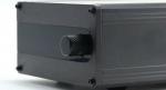
ePot.V4 LDR Preamp Controller & Stepped Attenuator With Optional Plug-in Solid State Buffer & Linear Power Supply

Tortuga Audio began work on LDR (light dependent resistor) based volume control in 2009 and went commercial with its first LDR based preamplifier in 2012. Over the past decade we’ve evolved our core preamp controller/attenuator design through four iterations. We are now developing our fifth iteration which we refer to the V4. Prior iterations included the V1, V2, V25, and more recently the V3.
This article discusses the upcoming V4 preamp controller & attenuator along with a new optional plug-in solid state buffer board and linear power supply, all currently in development. Given our upcoming move to Oregon and all that implies, a target release timeframe of 1st quarter 2024 feels realistic.
ePot.V4 LDR Preamp Controller & Stepped Attenuator
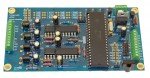
The ePot.V4 is a full featured passive, and optionally active, software based preamp controller combined with a unique 100-step electronic analog stepped attenuator that uses LDRs for audio volume control. The layout of the current V4 board prototype is shown in the CAD image below. At 2.7 by 4.4 inches, the V4 has the exact same physical dimensions as the current V3 model.
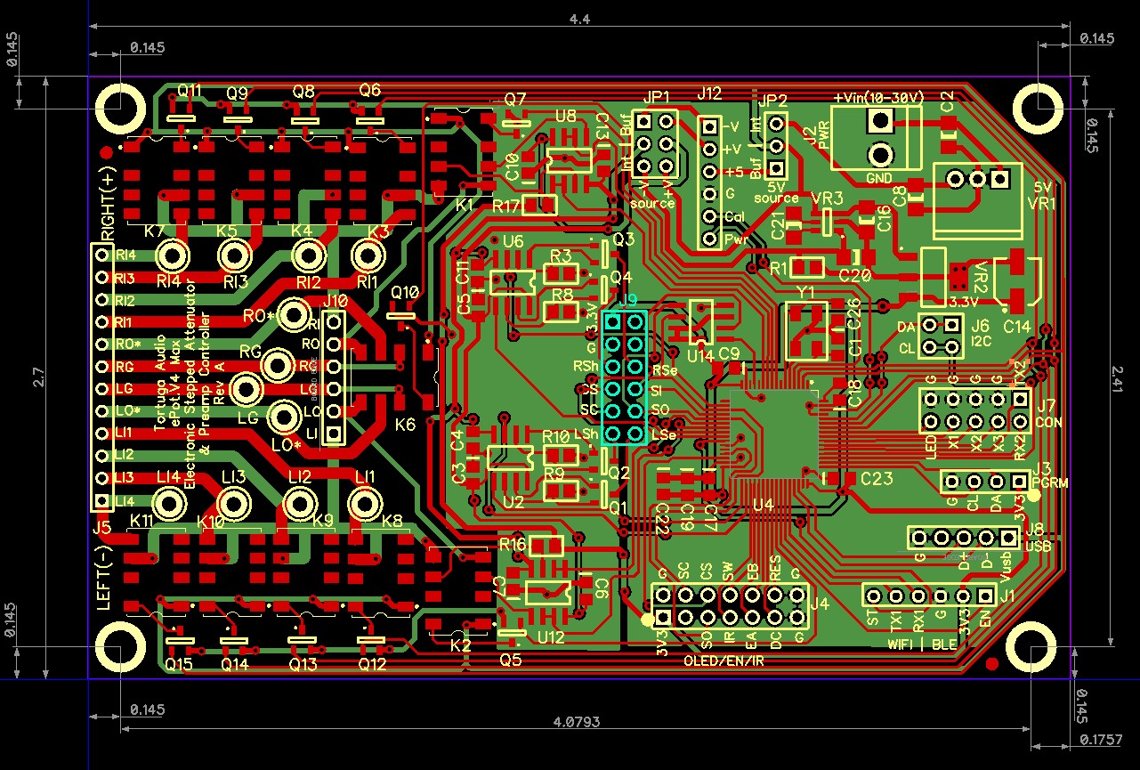
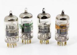
The heart of the V4 is Tortuga Audio’s precision closed loop LDR current control, first introduced in the V3, together with the ability to self-calibrate the LDRs in situ on demand. The V4 is driven by a 32 bit microcontroller running proprietary firmware developed by Tortuga Audio over the past 10+ years. LDRs are used because of their pleasing subjective sonic performance. Simply put, they sound nice. Clean, clear, colorless, natural and organic are typical adjectives that audio enthusiasts use to describe the audio performance of our LDR based preamp controllers and stepped attenuators.
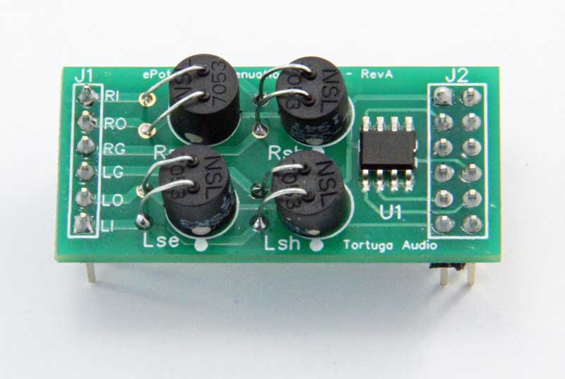
Each V4 employs 4 light dependent resistors (LDRs), 2 per each channel, that act as voltage dividers for stereo volume control. The 4 LDRs are mounted in a plug-in LDR attenuation module as shown to the right. This is the same LDR module type used by the V3. The LDR attenuation module also contains an EEPROM memory chip that holds the module’s LDR calibration data. Two pin headers, J1 and J2, plug into the J10 and J9 headers respectively on the V4 board. Should an LDR ever fail, it’s a simple matter to unplug the socketed module and replace it with a new one.
We do not pre-match the LDRs in our LDR based preamps. An LDR calibration cycle can easily be initiated by the V4 user during which the 4 LDRs are each automatically run through a sequence that adjusts and measures their resistance over 100 steps of volume control. The resulting 400 control settings are saved in the EEPROM memory chip and subsequently used internally by the preamp controller to set the desired volume level in response to the V4 user turning a volume control knob or using a remote control.
When equipped with our new optional plug-in solid state buffer buffer board, the V4 transforms from a unity gain passive 2 channel single-ended stereo preamp into an active volume controller with adjustable gain. Running 2 boards in parallel allows the V4 to be used for balanced stereo audio applications. We use the term “active” in this context in reference to the audio signal being acted upon by a power supply in the course of buffering and optionally amplifying the audio signal within the preamp. Most audio preamps are classified as “active” preamps, with passive preamps being in the minority.
Features of the V4
Features of the ePot.V4 preamp controller and stepped attenuator include:
- 2 channel stereo audio volume control
- Attenuation using LDRs (light dependent resistors)
- Single-ended or balanced audio applications (requires 2 boards for balanced volume control)
- Smooth 100 step attenuation with no sonic artifacts over a 60 dB range
- By itself serves as a high performance passive preamp/volume controller
- Becomes an active preamp with adjustable gain when mated with optional solid state buffer board
- Two totally independent stereo channels including independent audio signal grounds
- Remote control via infrared remote
- Local control via rotary encoder with integral pushbutton
- Nominal +/- 20 step (+/- 12 dB) channel balanced adjustment
- No electrical connection within the board between the audio signals and control power (optically isolated)
- Replaceable plug-in LDR attenuation module
- Built-in self-calibration of the LDRs – no pre-matching of LDRs required
- Switching between inputs (up to 4 stereo inputs)
- Audio signal connections to the board via either pin header or solder lugs
- Muting – kills the volume output by shunting output signal to audio signal ground
- Adjustable input impedance – default 50k plus 9 additional optional user determined settings between 1 and 100k
- Remote control via wifi/bluetooth (future – will require additional plug-in hardware)
- Menu driven control integration with external 256×64 pixel 8-bit grayscale white-on-black graphical OLED display (sold separately)
- Drives an optional status LED
- Auxiliary control output signals (up to 3) including power on/off trigger (TTL logic level)
- Communications via UART
- Communications via I2C
- Communications vis USB
- Firmware updating via USB thumb drive
- Powered by any 12 VDC external power supply with nominal 0.5A capacity
Key differences between the V4 and V3
We learn something new from every iteration of the ePot design and try to use that knowledge in designing the next iteration. We’ve taken knowledge gained from our history with the V3 to develop the V4 into the most refined LDR preamp controller & stepped attenuator to date. The key differences in the V4 as compared to the existing V3 are discussed below.
New processor chip
| Upgraded chip – The V4 employs a newer and faster chip that’s optimized for the type of analog control and measurement that the V4 design relies on. Fortunately, the new processor comes from a related family of chips from the same manufacturer thus allowing us to adapt our existing V3 firmware with minimal changes and without having to switch to a whole new set of development tools. |
| Optimized layout – The chip pin count was reduced from 100 to 64 while handling all the needed signals more efficiently and also taking up less board space. |
| Dual core – The newer chip is a dual core processor which makes it far easier to reliably update the firmware. |
| Higher accuracy clock – We opted to go with a more accurate external crystal clock for the V4 in order to allow the V4 to host a USB connection with a thumb drive thus eliminating the need to connect the V4 to a personal computer to update the firmware. |
| Eliminated an external DAC chip – The new processor allowed us to eliminate a costly, and sometimes difficult to source, external DAC chip used by the V3. The DAC functionality is now internal to the new processor. |
| More accurate measurement – The new processor’s ADC has effective 16 bit resolution thus making measurement during LDR calibration far more accurate. The V3 had only 12 bit resolution. |
Input count & switching
| Electro-mechanical relays – Unlike the V3 which used analog switches (IC chips), the V4 uses conventional miniature relays for input switching. Although generally successful, the analog IC switches used in the V3 series were found to be incompatible with certain audio sources where incoming audio signals would actually disrupt the operation of the controller by interacting with the power supply through the analog ICs. Otherwise the analog switches sounded and worked great. But to avoid this possible incompatibility in the future, we chose to use conventional electromechanical relays in the V4. re with minimal changes and without having to switch to a whole new set of development tools. |
| Only 4 inputs – The V4 can switch between 4 stereo inputs instead of 6 like the V3. The basis for this reduction in input switching capacity is keeping the V4 board the same dimension as the V3. A longer V4 board would be required to accommodate the additional relays required for 6 inputs. |
Power supply
| Updated internal regulation – The internal DC-DC converter design of the V4 is nearly identical to the V3 except a new negative voltage charge pump chip. As with the V3, the V4’s internal regulation takes incoming 8-30 volts DC and converts it to +5 and -5 volts via switching regulators and from +5 to +3.3 volts via linear regulation. |
| Optional power from buffer board – When the V4 is equipped with a SSB.V4 buffer board, all power to the V4 can be optionally switched over to come from the buffer board bypassing the V4’s internal power sources. This is accomplished via a pair of jumpers V4.JP1 and V4.JP2. In all instances, +3.3 volts microcontroller power is always provided by a linear regulator on the V4. |
| Optional linear power supply – When equipped with the optional LPS.V4 linear power supply, power to the V4 can come directly from the linear power supply via V4.J12 bypassing the V4’s internal power sources. Power from the LPS.V4 includes linear regulated +5 volts DC control power and +12 and -12 volt DC for powering the op amps. As with power from the buffer board, this also requires setting the jumpers V4.JP1 and V4.JP2 to the Ext position (external). When equipped with the optional SSB.V4 buffer board, the optional linear power would need to be supplied via the buffer board. |
| Optional high performance regulators – For those opting for the linear power supply, there’s an additional option to use high performance discrete linear regulators such as those made by Sparkoslab providing -125 dB input noise rejection, 3.2 microvolt output noise, and 2 millivolt load regulation. Those are outstanding specifications indeed. |
External input control header
| Header eliminated – The V3 has an 10 pin control header that allows the control of input switching devices external to the board. This feature was never utilized in any V3 builds that we are aware of. Therefore, this feature was eliminated in the V4 in order to save space and reduce pin count. |
Firmware updating via USB
| USB vs UART – The V3 board used a simple UART serial interface for firmware updating. Ostensibly simple, this required the use of an external USB-to-UART interface adapter to allow a required PC/MAC application to communicated with the V3 and update firmware. Moreover, the PC firmware updating application is itself fairly complex and cumbersome to use by the average end user. The V4 employs a direct USB interface with host capabilities eliminating the need for an externa PC or firmware updating application. |
| Firmware updating via USB thumb drive – V4 users will be able to download updated firmware on to a typical USB thumb/flash drive, then plug the USB drive into the V4 and initiate firmware update through the user control menu. No connection to an external PC or special PC based firmware application will be required. |
Muting relay
| Hard mute via grounding relay – Prior versions achieved muting indirectly by a combination of disconnecting the input signal and shunting the output signal to ground by minimizing the resistance of the shunt LDR. While generally effective, the output signal remained live and connected and under some scenarios could be subject to noise, audible artifacts, and even audible crosstalk. The V4 adds a grounding relay to achieve full muting by connecting the live output signal directly to audio signal ground thereby killing the output completely. |
Optional solid state buffer module
With release of the ePot.V4 we are also introducing an optional SSB.V4 solid state buffer module The buffer module is a separate printed circuit board that converts the V4 from a unity gain passive attenuator into an active volume control device with adjustable 0 to 12 dB gain. The buffer module has a high fixed high input impedance and a low fixed output impedance. This creates an electronic firewall turning the V4 into an active preamp platform compatible with virtually any audio source component and amplifier with no restrictions on interconnect length between the V4 preamp and any amplifier. Moreover, it gives the V4 additional dynamic authority that might be missing when used as a passive preamp together with source components and amplifiers that do not pair well with a passive volume control.
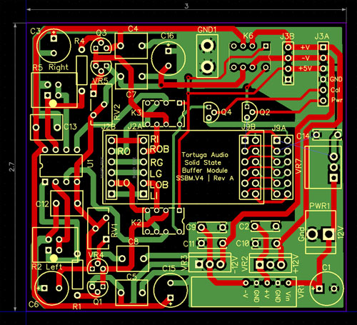
The buffer module board is the same width (2.7 inches) as the V4 board but at only 3 inches in length is 1.7 inches shorter than the V4 board. The buffer board mounts directly on to the V4 board using the same header sockets (V4.J9 and V4.J10) as the plug-in LDR module. Pin header J3A also mates with the V4.J12 power socket. To complete the install, the LDR module is then plugged into the buffer module board itself. The finally assembly becomes a 3 layer sandwich with the V4 at the bottom, the buffer board in the middle and the LDR module on the top.
When using a buffer module, incoming power connects directly to the buffer board instead of the V4. The buffer board takes care of routing power to V4 through the J3A power header. The buffer board can be powered two different ways. The first option is to use any external DC supply from 8 to 30 V with a nominal 1A capacity similar to the V4. This powers a series of switching and linear regulators to produce +5V control power and split +/- 12 volts for the op amp input stage and discrete JFET buffer output stage. for The second option is to use our new optional linear power supply that provides similar voltages but from a very clean, low-noise linear regulated power supply to achieve the best possible sonic performance. Power output from the optional linear power connects to the buffer board via the J3B header.
Buffer module features
The buffer module design includes the following features:
- Plugs directly into V4 board – no other mounting hardware required
- Transforms passive V4 attenuator into an active preamp
- 2 channel active stereo buffer with optional gain
- 0 to 12 dB adjustable gain via plug-in gain modules
- High impedance socketed audio op amp IC input stage | user can substitute other op amps
- Optional high-end discrete op amp for those willing to pay a premium for ultimate performance
- Low impedance audio JFET output buffer stage
- Direct coupling – no input or output coupling capacitors
- Tight integration with the V4 board – plugs directly into the V4
- Manual trim-pots for zeroing DC offset of the output signals
- High quality Elna silk audio grade electrolytic power supply bypass caps
- High quality polypropylene film power supply bypass caps
- On board split voltage switching DC-DC power converter
- Optionally powered by external split voltage linear power supply
Optional linear power supply
The optional LPS.V4 power supply board is a source of clean, low-noise power for the ePot.V4 board with or without the optional buffer board. It’s a tri-voltage board delivering +5 volt control power, and the split +/- 12 volts needed for powering op amps and the buffer.
The premise behind the linear power supply board is that despite the advances and ubiquitous nature of switching power supplies for audio applications today, clean, low-noise linear power remains the gold standard for powering the low-level audio signals in high performance preamplifiers. That said, the LPS.V4 does indulge slightly in the use of switching technology in that it relies on a 6.5 volt switching DC-DC regulator upstream of the linear 5 volt regulator that delivers control power however this power does not interact directly with any audio signals.
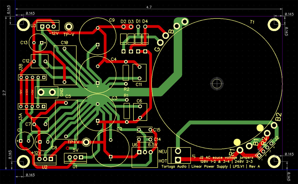
This LPS.V4 uses the best of traditional linear power supply design and components including toroidal transformer, low noise Schottky rectifiers, ample filtering, and high quality Elna electrolytics and Wima/Vishay polypropylene film bypass capacitors. All voltages are managed by linear voltage regulators with the option to use high-end low ripple/noise super regulators for those willing to pay a premium for the very best.
Linear power supply features
The linear power supply offers the following features:
- Fused AC mains input power | 120 or 240 VAC selectable via jumpers
- Low-noise 10 VA toroidal transformer
- Super fast low-noise full bridge Schottky rectifying diodes
- Tri-voltage linear regulated DC output | +5 volts for control, and split +/-12 volt for audio
- All linear voltage regulators equipped with thermal and overload protection
- Optional use of high performance super-regulators capable of 125 dB ripple reduction (compared to typical 50-70 dB)
- High quality audio grade Elna silk electrolytic and polypropylene film bypass capacitors
- Layout follows best practices star grounding