OLED display assembly
$175.00
The OLED display assembly is a high contrast 256 x 64 pixel white-on-black graphic OLED (Organic Light Emitting Diode) display for use with Tortuga Audio’s V25, V3 and V4 series preamp attenuator/controllers and related Tortuga Audio preamps.
The OLED display assembly provides an easy and intuitive user control experience through an interactive menu driven control interface designed around the 7-button Apple remote.
The display assembly includes a custom adapter board with installed infrared (IR) receiver module and a header for connecting an encoder module. All cabling is included. The unit is fully tested and ready to go and requires no assembly per se.
Please note however that mounting hardware is not included and is entirely up the buyer.

Overview
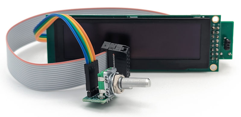
The OLED (Organic Light Emitting Diode) display assembly combines a 3.2 inch, 256 x 64 pixel OLED graphic screen with a custom adapter board, a rotary encoder, and an infrared receiver module to create an integrated OLED display assembly for Tortuga Audio’s LDR stepped attenuator and preamp controllers. It’s a bright, high contrast, white-on-black display with no backlighting. Overall brightness is user adjustable over a 14 step range.
The OLED display assembly is a key part of the menu driven man-machine visual control interface used by all Tortuga Audio preamp controllers and products including the V3 and V4 series. The OLED display replaced Tortuga Audio’s earlier 7-segment displays.
The OLED display assembly was originally released in June 2018 for use with Tortuga Audio’s V25 preamp controller board. There have been 5 revisions to the OLED display assembly designated as A through E with E being the current version. These revision are discussed in more detail below.
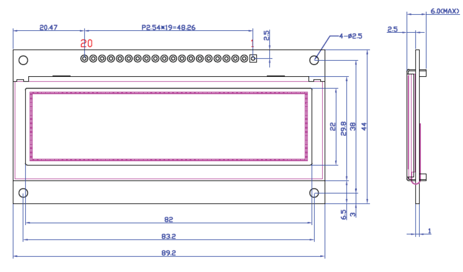
Display board
The display assembly uses a 3.12 inch (diagonal) OLED screen screen manufactured by EastRising designed around the Solomon Systech SSD1322 OLED driver/controller. The 256×64 pixel graphical screen renders 16 shades of white on to a black background.
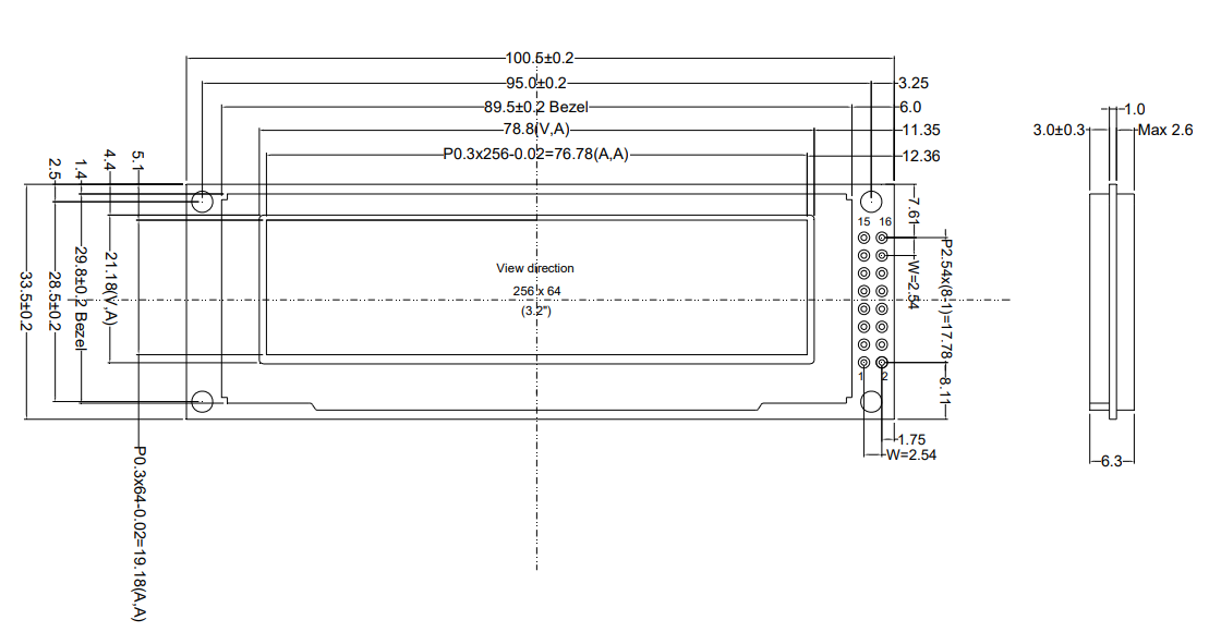
The display board is equipped with a single 16-pin dual row control/power header. Connection to the display board is handled by Tortuga Audio’s custom adapter board described below.
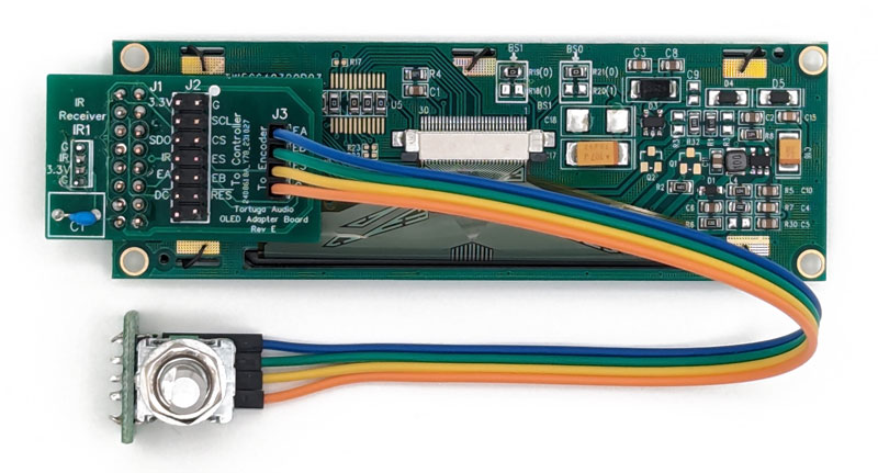
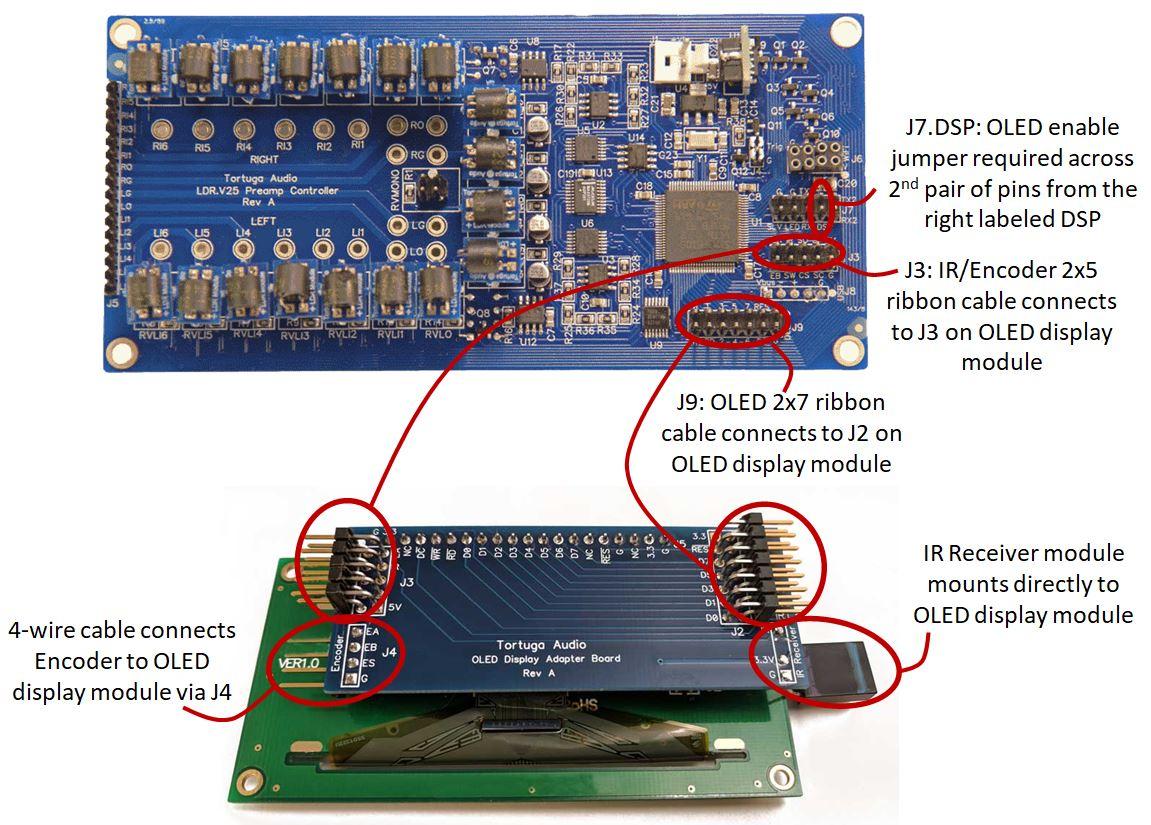
Adapter board
Tortuga Audio’s custom adapter board is soldered directly to the OLED screen board via J1. The adapter board includes a 14-pin J2 interface header for connecting the display assembly to a Tortuga Audio preamp controller board via a ribbon cable. The adapter board also includes a 4-pin J3 header for connecting to a rotary encoder (manual volume/control knob) via a simple 4-wire cable. The adapter board also has a solder pad for attaching an infrared remote receiver module.
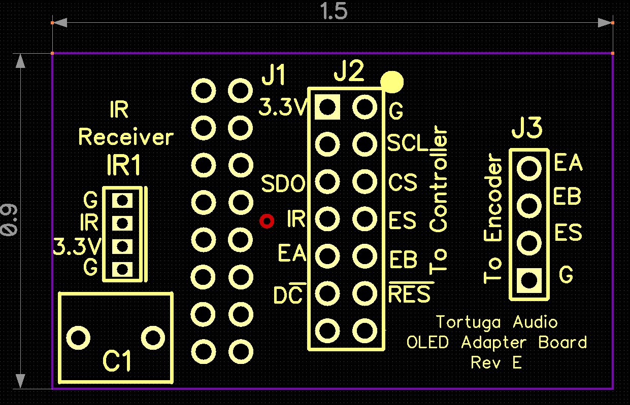
J2 | control header
All power and control signals for the OLED screen, the encoder, and the infrared receiver are routed through a single 14-pin ribbon cable that connects to the J2 pin header on the OLED adapter board. The other end of the control cable connects to a corresponding OLED pin header on the a Tortuga Audio V25, V3 or V4 preamp controller board.
- 3V3 – power (clockwise)
- G – ground
- SCL – SPI clock
- CS – SPI display chip select
- ES – encoder switch
- EB – encoder leg B
- RES – OLED display reset
- ** no connection **
- ** no connection **
- DC – OLED display data/command
- EA – encoder leg A
- IR – infrared receiver signal
- SDO – SPI data
- ** no connection **
Please note that the ribbon cable connector ends are NOT keyed and thus can be connected in reverse. While this is unlikely to damage equipment, please be careful to make sure the red stripe on the ribbon cable is on the same side of each header that has a white dot the circuit board (i.e. align the red stripe with the white dot).
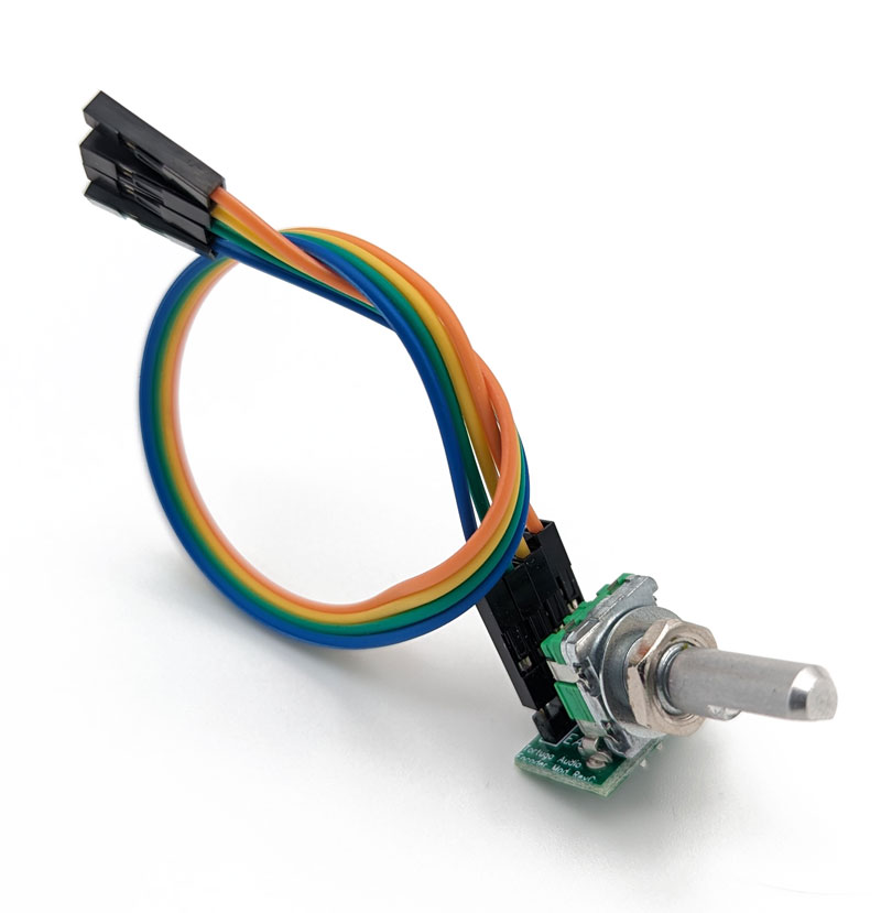
J3 | encoder header
The rotary encoder provides a means of manually controlling a Tortuga Audio preamp controller. However, the sole means of connecting the encoder to a preamp controller is through the OLED display assembly. The encoder connects to the OLED display assembly via the 4-pin J3 header on the adapter board. The J3 connection notwithstanding, the encoder has no direct connections to the OLED display itself.
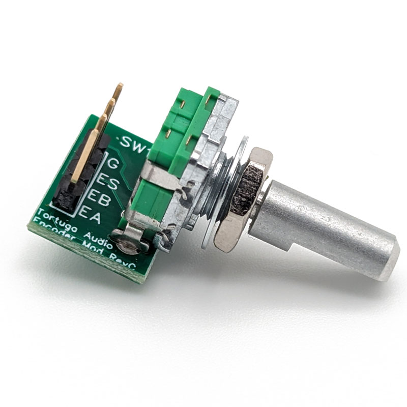
The J3 encoder header pin out is listed below.
- EA – encoder leg A
- EB – encoder leg B
- ES – encoder push button switch
- G – ground
Please note that if turning the encoder clockwise lowers rather than increases the volume, that you can simply swap the position of the EA (leg A) and EB (leg B) connections to correct this.
Also, note that the encoder module itself can be purchased separately here.
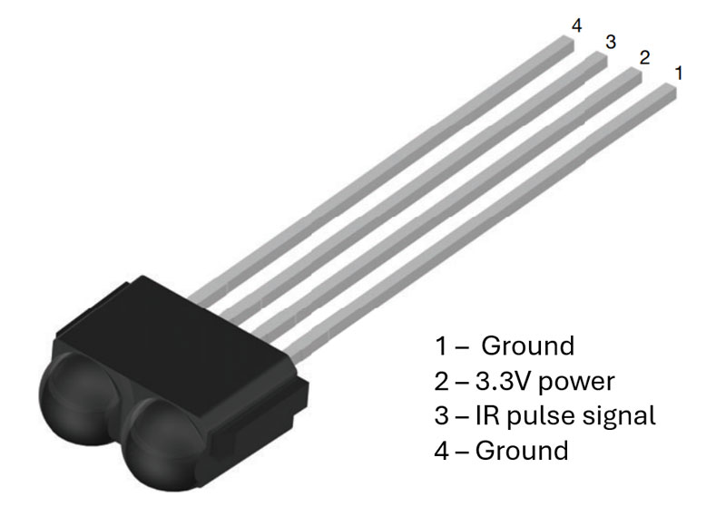
IR1 | infrared receiver module
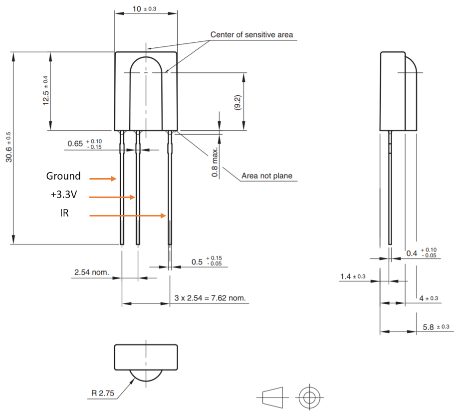
The 4-wire infrared (“IR”) receiver module is soldered into the end of OLED adapter board where the adapter board extends slightly beyond the edge of the OLED display screen. This allows the IR receiver to “see” out into the listening room assuming the OLED display assembly is mounted into the front panel of a preamp and thus is itself facing out into the listening room.
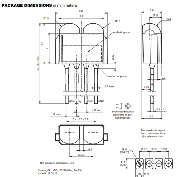
As with the encoder, the IR receiver has no connections into the OLED display screen itself. It sends its signal to an attached Tortuga Audio preamp controller board via the same 14-pin ribbon cable used by the encoder and the OLED display.
The IR receiver pin out is as follows:
- G – ground
- IR – received signal pulse
- 3.3V – power
- G – ground
Hardware versions
The have been 5 versions of the OLED display assembly designated A through E. Versions A, B & C use a NewHaven OEM display while version D & E use an EastRising OEM display. Both OEM versions utilize the same underlying OLED display SSD1322 driver and perform identically.
The table below summarizes the differences between each version and their compatibility with Tortuga Audio controller boards.
| Criteria | Version A | Version B | Version C | Version D | Version E |
|---|---|---|---|---|---|
| Adapter board interface to OEM board | 1x22 pin horizontal header (top) | 1x20 pin horizontal header (top) | 1x20 pin horizontal header (top) | 2x8 pin vertical header (right side) | same as D |
| Display module OEM | NewHaven | NewHaven | NewHaven | EastRising | same as D |
| Connections to Tortuga Audio controller board | * 14 pin parallel - display signals only * 10 pin - for IR receiver and encoder signals only | * 14 pin serial SPI - display signals only * 10 pin - for IR receiver and encoder signals only | 14 pin serial SPI - for display signals, IR receiver and encoder | 14 pin serial SPI - for display signals, IR receiver and encoder | same as D but with a smaller more compact adapter board. |
| V25 - Rev A | Compatible | Not compatible | Not compatible | Not compatible | Not compatible |
| V25 - Rev B | Not compatible | Compatible | Compatible - requires IR receiver and encoder to be connected individually to V25.J3 header and not through the OLED display interface board | Not compatible | Not compatible |
| V25 - Rev C | No compatible | Not compatible | Compatible | Compatible | Compatible |
| V3 & V4 | Not compatible | Not compatible | Compatible | Compatible | Compatible |
Legacy hardware info
NewHaven display screen
A NewHaven OEM display screen was used in version A through C and had either a 22 or 20 pin horizontal control pin header along the top. The Tortuga Audio adapter board (not shown here) was soldered to the NewHaven OEM display via the horizonal pin header.
Secondary ribbon cable
Version A display assembly used a second 2×5 IDC ribbon cable to carry encoder and IR receiver signals. This cable ran between the 10 pin V25.J3 header and the its corresponding 10 pin OLED.J3 header on the adapter board of the Rev A version of the OLED display module.
OLED display assembly versions B onwards do not use the second ribbon cable.
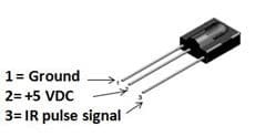
IR receiver module
OLED display assemblies prior to June 2021 used a different 3-wire IR receiver module.