V25 firmware updating

Print Friendly, PDF & Email

Who should read this section?

If you’re new to Tortuga Audio preamps and/or you are considering updating the firmware of your V25 based preamp for the first time, then we recommend you read this section first.

If you’re a tech savvy audiophile who everyone comes to for help with their computers then you can probably skip this overview and go directly to the next section in this series which discusses how to obtain a firmware update and how to install it on your V25 preamp controller.

What is firmware?

All of Tortuga Audio’s preamp’s  are controlled by a software driven microcontroller which is a type of embedded microprocessor widely used in commercial, industrial and consumer equipment. The software running on the microcontroller is referred to as “firmware.

Firmware is a class of computer software that controls a specific hardware device and is typically stored in that devices’s read only memory. By its nature firmware is neither easy to erase nor is it easy to replace or update especially as compared to software applications that run on a personal computer. Firmware usually runs directly on a microcontroller’s “bare metal” without any intervening operating system.

Why update your firmware?

The simple reality with software is there are always bugs that need fixing and new features and capabilities that keep getting added. Most  of the time the casual owner of equipment can ignore all that. But sometimes the bug is significant and once the fix is in the only way to get that fix into your machine is to do a firmware update.

Firmware Versions

Firmware for the V25 can be divided into 2 periods – before OLED and After OLED.  OLED refers to the graphic OLED (organic light emitting diode) display introduced in May, 2018.

7 Segment Display Only Firmware – Before introducing the OLED display our displays used 7-segment display technology with a 2 digit left channel and a 2 digit right channel numerical display. The firmware version was nominally a 4 digit number that started with the numbers “10” on the left followed by the actual version on the right. This series started at 1001 and went up through 1029 before this firmware series ended when the OLED display came out.

New Firmware Series For Both Display Types – When the OLED display was introduced, a new firmware series was started that applies to both types of displays. The same firmware operates either display. The new firmware versioning uses a 3 digit number plus an additional leading “0” which you can ignore. The new versioning started with version 201 and has since had over 30 subsequent updates most of which were minor fixes or improvements.

Which firmware version do you have?

Your preamp is able to display the version number of your firmware. It’s done differently depending on whether you have the original 7-segment display or the newer OLED display.

7 Segment Display – The firmware version will flash briefly on the display roughly 5 seconds after power is applied to your V25 preamp. To be clear, the firmware version does NOT display when you turn on the preamp but only when you apply power to the preamp. The firmware version will be a 3-4 digit number like 1025 or 0232.

OLED Display – On preamps with  an OLED display you can scroll down the menu tree until you see the “Version” menu item. Press Enter on the remote and it will display the preamp model number, hardware version, and firmware version.

Special consideration when upgrading beyond version 1011

If your preamp currently has earlier series firmware version between 1001 and 1011, please read the following information carefully before proceeding with a firmware update.

If your preamp currently has firmware versions 1011 (or earlier), updating your firmware  will cause your preamp to go through a mandatory automatic re-initialization process. This is a one-time process but must be allowed to run to completion in order for the update to become effective. If interrupted, the automatic re-initialization process will repeat itself the next time your preamp is powered up until the process is allowed to run to completion.

Duing this re-initilziation process your existing impedance settings and associated attenuation/calibration tables will all be deleted. Various numbers may be displayed during this process. When the first phase of the re-initilization process is complete your preamp will then automatically enter the second phase where it automatically runs through a calibration cycle associated with impedance setting #1 which will now become fixed at 20k ohms by default. When the calibration process is completed your preamp will reboot and then turn itself on after which it will be available to be used normally.

If for whatever reason your preamp does not operate properly after such an update, please run the calibration process 1-2 more times.

Users with balanced preamp will need to repeat this process with both V25 boards. When updating the left board there will be no information displayed. Please allow at least 15 minutes after uploading the firmware to allow the automatic re-initialization process to complete even if no information is displayed.

With this upgrade, setting/level #1/20k will no longer be available to be edited by the user as before. Only settings 2-9 will be available to the user to setup and adjust input impednace between 1-99k ohms.

Procedure overview

Updating your preamp’s firmware requires the use of a bootloader program running on a PC together with the latest firmware “hex” file. You can download both the bootloader application and the firmware file from our website.

To execute the actual upload process you:

  • Unplug your preamp from its power source
  • Start the bootloader application program on your PC
  • Then plug in the USB cable from your PC into the preamp
  • Depending on the version of your V25 hardware you might also have to plug power into your preamp.
  • At this point you have a 5 second window to connect the bootloader app to the preamp (details on this below)
  • Once connected, you select the firmware hex file you previously downloaded and stored on your PC, and upload it into your preamp. The actual upload proper takes less then 5 seconds.

The rest of this document elaborates on the firmware updating process described above.

The bootloader

The (mikro)Bootloader  is a small PC based software application that you use to establish USB communications with, and upload new firmware into, the V2/V25 preamp.

Unfortunately the Bootloader is a PC/Windows only application. There’s no MAC version currently available. We are not anti-MAC, but the supplier of our programming tools stubbornly refuses to provide a MAC version of the Bootloader program while providing no reasons for not doing so.

The Bootloader program is a simple executable file (mikroBootloaderUSBHID.exe). Unlike conventional software, it does not have to be installed/registered into your PC. The program file simply has to reside somewhere on your PC. We suggest you download it to your PC desktop. The first time your run this program (by double clicking on it) it will create a small text file named “settings.ini” in the same directory. No special drivers are needed. It doesn’t install or change anything in your PC. If your PC has a USB port, you should be good to go.  We know the Bootloader works with Windows 7, 8 and 10. It may also work with  older versions of Windows but we haven’t tested that. To remove the Bootloader program from your PC simply erase both the  mikroBootloaderUSBHID.exe and settings.ini files from whatever directory you put them in.

You only need to download the bootloader application one time since it rarely if ever changes. Please find the download link below.

bootloader download
V25 Mikro Bootloader program file: Rev 2.7

Download the firmware file

Click on the link below to download the firmware file. Store the file in a convenient place on your PC and remember where you put it. You will need to find it later on.

The file itself is a text based “hex” file. It’s perfectly safe to download it. You can view it with any text editor or word processor if you’re curious what it looks like.

When you try to download the firmware file it may show up as lines of text in your browser. In that case right-click on that browser page and do a “save as” to download the actual file to your computer.

download button
V25 firmware file:  Revision 2.3.5

About USB cables – important!

The #1 problem that people encounter when trying to update their firmware is the inability to make a connection. In most cases this is caused by their USB cable.

Most of us have several USB cables laying around because we have cell/smartphones and other devices that use USB cables for charging. Unfortunately, many of those USB cables are for charging only and lack the ability to transmit data.

“Charging only” USB cables will not work with the bootloader and firmware update system! You need to use a proper USB “data” cable that has the conductors for the D+ and D- USB data signals.

Finished Preamps

All finished Tortuga preamps require a USB cable with type A male connectors on both ends. The cable is supplied with all finished Tortuga Audio preamps. Connecting the cable does nothing by itself. Your PC should not react.

DIY Boards – Micro-B Socket

If you have an older V2 LDR3x DIY board with a micro-B socket board soldered to the J8 header on the board you’ll need a cable with a male A end and male micro-B USB end. An LED light on the micro USB connector breakout board on the V2 will light up once it’s connected to your PC.

DIY Board – Tortuga USB Connector

If you are using a Tortuga USB connector cable with the female end connected to the J8 header make sure you have the female end connected such that the red wire is next to microcontroller end of J8 header and not the end with the white dot.

Step 1 – Preparation

Download the bootloader application

The Bootloader application is a small Windows executable (.exe) application file. You only need to download it once and keep it handy somewhere on your PC. See the link above to download the application.

Download the firmware file

Please refer to other sections within the V25 firmware topic for downloading the firmware file itself. Store the file on your PC somewhere where you can easily find it.

The firmware file is referred to as a “hex” file because it’s a text file wherein the code is formatted using a specific hexadecimal protocol and file uses a .hex file type suffix.

Remove power from your preamp

This is key and often confuses people so read carefully. The Bootloader is only able to connect to your preamp during the 5 seconds after power is applied. If the connection hasn’t been made during that 5 second start-up period you have to remove power and try again.

Connect your USB cable to your PC but NOT to the preamp

Please not this carefully. DO NOT CONNECT YOUR USB CABLE TO YOUR PREAMP YET!! But please do connect one end to your PC.

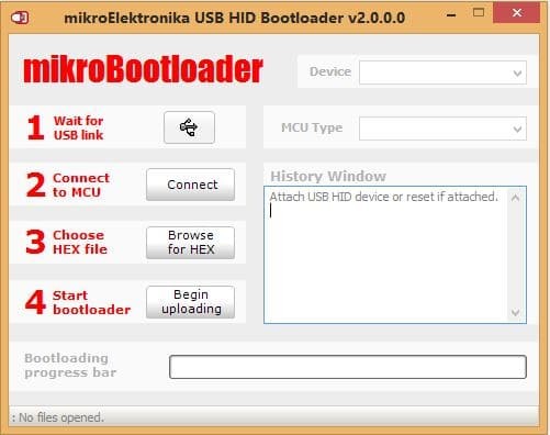
Step 2 – Start the bootloader program

When the Bootloader program starts it will look more or less like the pic below. At this point it won’t be doing anything except waiting.

bootloader_1

This is perhaps the trickiest and most confusing part of the process. All V2 boards and earlier Rev A versions of V25 boards require that power be plugged into the preamp to initiate the 5 second bootloader connection window. Later version B & C of the V25 board can be powered directly from their USB connection. Hence the following procedure differs slightly depending on the hardware model/version you have.

  1. Apply power to your preamp
    1. V2 & V25-RevA preamps
      1. Connect USB cable to the V25
      2. Connect power to the V25
    2. V25-RevB/C preamps
      1. Only connect USB cable to the V25 (not power)
  2. The little USB symbol to the right of “1 Wait for USB link” should turn red
  3. The Device window should display “LR3x.V2 Board” or “LDR.V25” or similar
  4. The MCU Type window should display “PIC18” or “STM32F” or similar
  5. The History Window should say “Waiting MCU response…”

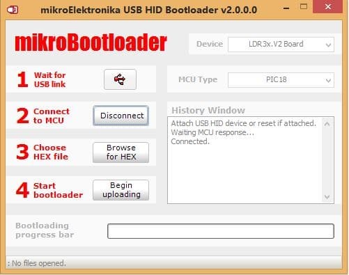
At this point you will have 5 seconds to establish a USB link between your PC and preamp by pressing the “Connect” button next to “2 Connect to MCU”. If all goes well, the “Connect” button text will change to “Disconnect” and the History Window will now say “Connected” as shown in the pic below. If you run out of time, don’t panic, just remove power again, wait a few seconds and then reapply power to the preamp which restarts the 5 second Bootloader timer.

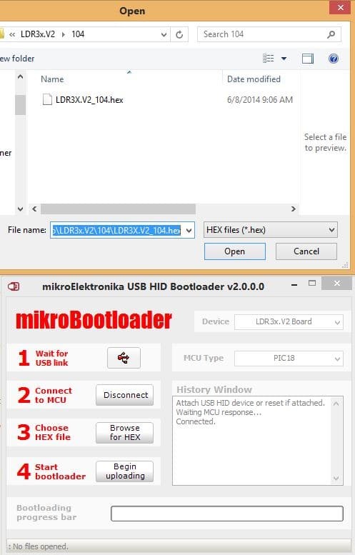
Step 4 – Choose the firmware (.hex) file

Select your firmware file by pressing the “Browse for Hex” button next to “3 Choose HEX file”.  This will open a file dialog box. Find your downloaded .hex file stored on your PC and click the “Open” button. At this point the firmware is ready to be uploaded into the preamp board.

Step 5 – Upload the firmware to your preamp

Press the “Begin uploading” button next to “4 Start bootloader” to upload the firmware into the preamp. The previous firmware build will first be erased and then the updated software build will be written to the preamp’s microcontroller chip. This erase/write operation is very fast and should take less than 5 seconds to complete.

You should get a “Success” message. Click the  “OK” button to close the message box. Note the new messages in the History Window. Upon a successful write, the Bootloader program will automatically disconnect from preamp and the preamp will reboot which takes 5 seconds.

You are now done and can close the Bootloader program, disconnect the USB cable, and enjoy your updated preamp.

bootloader_4

Firmware changelog

Click on the shaded bar below to expand and view the V25 firmware changelog.

Rev/Date
Description
235 – 05.25.20* Change – Improved the master=>slave communication updates during impedance setting/level changes
to ensure changes stay in sync between master & slave boards in balanced setups
* Fix – Added missing saves of imped data during setting/level edits under certain conditions
234 – 03.16.20* Change – LDR3000T default #1 impedance level changed from 20k to 80k to improve baseline sound quality
233 – 01.28.20* Fix – Corrected channel balance for LDR3000T/P models when using balanced inputs. Single-ended inputs not affected.
232 – 12.4.19* Fix – Simplified screen saver and display timeout logic in order to avoid intermittent glitch when exiting screensaver mode
* Tweak – added to “T” to version text LDR3000T.V25
232 – 12.4.19* Fix – Simplified screen saver and display timeout logic in order to avoid intermittent glitch when exiting screensaver mode
* Tweak – added to “T” to version text LDR3000T.V25
231 – 10.24.19* Fix – Prevent screensaver from kicking in when unit is going through cal
230 – 10.15.19* Change – updated phase reversal logic to allow assignment of phase reversal to LDR3000T balanced inputs 1, 2 and 3
229 – 10.09.19* Tweak – Added automatic fix to default input label if stored label is found to be blank (deleted)
* Fix – Corrected bug introduced in rev 228 relating to changes in muting command
228 – 10.07.19* Change – Master now sends only _mute or _unmute commands to slave board instead of the ambiguous _mute_toggle. This helps avoid the two boards getting out of sync with each other in balanced configurations.
227 – 9.21.19** This update mostly related to the new LDR3000T model **
* New – Added ID etc for LDR3000T model preamp
* New – Added buffer messages to send commands to TPB.V2 buffer board chip
* New – Added tube buffer board startup sequencing for LDR3000T.
* New – Added tube buffer mute/unmute for the LDR3000T
* Fix – Modified channel balanced for LDR3000T RCA inputs (4, 5 & 6) . This was required because both the right and left channels each use the “right” channel on both the master and slave boards. Prior to fix the channel balance wasn’t working for the RCA inputs.
226 – 8.23.19* New – Added Encoder type menu item. There are now 2 possible encoder types (1 and 2). The original type 1 is the default. The newer type 2 was introduced around August of 2019. User can change the type. If the wrong type is selected the encoder will still work but may double count or half count the encoder pulses.
225 – 6.27.19* Change (only applies to preamps with 7-segment displays): The previous method of starting/stopping Calibration while the unit is off has been eliminated. Calibration is now initiated by pressing the Mute (lower right hand) button on the remote while the preamp is in Impedance Adjust mode. This will initiate calibration at whatever impedance setting/level the unit is set at prior to pressing the Mute button. This change makes the calibration start/stop control scheme with LED displays essentially the same as with the newer OLED display. As before, please be aware that if you have multiple impedance setting/levels configured you’ll have to repeat the calibration cycle for each setting/level individually.
* Fix – Force volume control menutype to always be “balanced” by default when display type is 7 segment LED
224 – 6.4.19* Fix – Added missing test for SPI vs. parallel communication for OLED during first board initialization

223 – 5.30.19* New – Added V25_RevC to hardware types and amended code to reflect Revs A, B and C
* New – Switched OLED communications over to SPI for V25_RevC hardware
* Fix – Changed SPI communication mode to conform with main DAC latching data on falling clock.
* Fix – Volume step was showing +1 higher than actual level when MaxVol limit kicked in during input change
* Tweak – refined volume controls to ensure unit muted/unmuted properly anytime user manually reduced volume to zero and then raised it back up to 1
* Tweak – modified 2 sec delay in volume control so that it only took effect when unit transitioning to off state

222 – 4.25.19* Tweak – improved reliability of cal status info communications between balanced boards
221 – 3.15.19* Fix – Timed out display would not awaken easily after being off for extended periods. Problem involved a counter rollover/overflow.
220 – 2.27.19*Change – ** Important Change To Menu Structure Related to Impedance & Calibration **

This changes provides a more logical and consistent set of controls around the closely related topics of impedance and calibration. Going forward, this change now makes it unlikely to accidentally start calibration.

1) The separate Cal and Imped menu items have been combined into a single Imp-Cal menu item.

2) When the Imp-Cal menu item is selected, the user will see the Impedance Control Action display where the impedance setting/level can be changed.

3) While in the Impedance Control Action display the use of the Enter and Menu buttons now work the same as all other displays and Calibration can only be started via the Mute button
a) Enter returns the unit to the default Volume Control Action display.
b) Menu escapes back out to the Imp-Cal menu list item.
c) Calibration can now only be started by pressing the Mute (lower right) button causing the display to switch to the Calibration Control Action display.

4) When viewing the Calibration Control Action display
a) Enter button will quit calibration and return the unit to the default
b) Menu button will quit calibration and escape back out to the Impedance Control Action display

*Fix – If user was playing music while switching to an impedance setting that had not been set up yet (setting was “off”) the volume would briefly surge before muting.
219 – 12.11.18*Change – Minor improvements to handling remote commands plus various modifications related solely to the future V3 board
218 – 12.5.18*Fix – Escaping from Imped menu after changing impedance setting # was causing reversion back to prior setting #

217 – 11.27.18*Change – Addition of various options related solely to the future V3 board. Has no direct impact on V25 operation/performance.
216 – 11.13.18*Change – Slowed down the responsiveness to remote inputs to avoid unintended command repeats.
*Change – Raised Vref index limit from 2500 to 3000 for marginal LDRs to reach 100R target during VRref phase of calibration
215 – 10.23.18* Change – Not a change per se but entire code was scrubbed and edited to make everything case sensitive going forward. This warranted to revision just in case there were any resulting issues (none found yet).
214 – 10.15.18* Change – improved inter-board communications for dual board balanced systems
* New – Add Phase Inversion option for dual board balanced systems that are wired appropriately.
* New – Modified menu structure to allow for 3 different options for how volume display handles
channel balance, input change and inverse phase (see Preamp Controls in online documentation for details).
213 – 9.25.18* Change – Made sure primary LDRs isolated from buffer before turning on buffer
* Change – Added auto-start of cal cycle as last step in unit reset process
212 – 9.7.18* New – Adapted for SSB.V1 solid state buffer integration – added external Mute_Out output
* Change – Modified turnoff code so that unit would first ramp down volume before turning off
* Fix – Forced display to turn on and update when waking up from blanked display timeout
211 – 08.16.18* Fix – When muted, preamp would ramp down to zero volume and then immediately ramp back up again. Only a few users experienced this behavior because it only happened after switching inputs using the slow mode. Using fast input switching would not trigger this mute yo-yo behavior. A simple fix but took us a good while to figure this out since most units did not exhibit this behavior.
210 – 08.6.18* Change – LDRs now initialize upon power boot up rather than waiting until after 1st turn on & unmute
209 – 07.3.18** This update fixes a lurking bug in the Cal routine where Cal was not disconnecting the preamp’s outputs during the calibration process. This could lead to erroneous calibration results of hung calibration if IC cables were left plugged in.
* Fix – Initialization of input labels when first converting existing units to OLED firmware
* Fix – Outputs were not disconnecting during cal which is why leaving output
IC’s attached to preamp during calibratoin was causing difficulities with cal.
208 – 06.28.18** This update deals mostly with bugs and improvements related to adjustable impedance and cal.
* Fix – Inhibit screensaver when not set to volume control display
* Fix – Corrected logic that allowed impedance settings higher than 10
* New – When user quits cal and cal has not been previously completed for current setting/level (i.e. it’s a new setting/level), the new imped setting/level get deleted (i.e. setting gets turned off) and preamp reverts to default 0/20k imped setting/level
* Tweak – Added explicit instructions to impedance display when changing levels – “Set to Off or press Enter to start Cal”
* Tweak – Improved logic and inter-board coordination related to user manually stopping cal
* Tweak – Improved reliability of multiple boards remaining in volume sync
207 – 06.23.18** This update addressed a key bug when updating existing V25 boards to OLED firmware for the 1st time. Also corrected a potential problem if user did not wait for boot up or turn-on splash screens to finish before issuing remote commands **
* Fix – Force initialization of input labels when updating V25’s to OLED firmware 1st time
* Fix – Input label edit was not returning to volume control display properly upon pressing Enter
* Fix – Input labels not displaying properly
* Fix – Added command input inhibit during boot up, turn on and turn off transitions to prevent control lock-up
* Fix – Input count value was being overwritten at boot up
* Fix – Inhibit screensaver timeout while Cal is running
* Change – Increased Cal VLo target and slightly relaxed the VLo closure error to avoid getting caught in a needless cal loop that served no purpose
* Tweak – Formatting clean up to Cal info display
206 – 06.18.18* Fix – 7Seg Cal Mode didn’t display 0 – 0; made it conform with prior behavior
* Fix – Precal startcount display ignored count 3-5
* Fix – Bug with saving VLo index created with version 204
* Change – Toggle between volume display Units can now be done using either Raise/Lower buttons
* Fix – Volume last associated with each input was being overwritten during power reboot
* Change – Starting Cal no longer clears cal status flag. Only changing imped level can now clear this flag and force calibration.
205 – 06.13.18 Fix – height of volume bar varied with brightness level
204 – 06.12.18 Tweak – factoring of the cal.c main loop code to tighen up the process
New – added LDR3_V25K model
203 – 06.06.18** Miscl fixes **
* Fix – Master was not receiving slave count in init.c
* Fix – Cal.c was not unmuting (reconnecting I/O) after cal was done
* Fix – Slave was not being allowed to turn off cal when done
* Fix – Volume not positioned properly in display when volume.ramp dropped below 10
202 – 06.01.18** 7-sement display compatibility update. Numerous fixes to ensure the 7-segment display continues to work normally **
* Fix – Added missing display type switches to Cal.c & Imped.c
* Fix – Preamp would immediately mute when turned on via Encoder pushbutton
* Tweak – moved interrupt call to menu handler from volume.c to timer.c (this has since been reversed)
* Fix – corrected info display during precal
201 – 05.29.18
THE “OLED” RELEASE
** Initial release of firmware with OLED display feature. **
* New – Added OLED display capability
* Change – Complete overhaul of menu controls
* Change – Numerous changes under the hook to improve reliability and operability
1029 – 04.18.18* Fix – 1028 introduced a bug where fast switching input via left button press would result in selecting input +1 higher than max # of inputs available.
1028 – 04.15.18* Fix – Last volume levels associated with each input were not being properly saved in all instances.
1027 – 04.12.18* Tweak – Modified Cal VLo to ensure only lowest value of VLo is saved for both the left and right sides during the VLo cal process.
1026 – 04.6.18* Change – Force system reset at conclusion of auto cal to ensure slave units properly reset after cal process. CalReset flag set in eeprom tells unit to turn on after reset and clears the flag.
1025 – 03.16.18* Fix – Output was not muting properly when volume was manually set down to zero.
1024 – 01.18.18* Fix – Firmware was hanging intermittently at turn off (Mute + Down).
1023 – 1.18.18* Change – internal release related to changes in how pre-calibration is initiated (for factory use only)
1022 – 1.8.18* Change – Eliminated support for Tortuga Audio legacy remote. Code was responding to input from various non-Tortuga remotes that use the NEC protocol and same remote ID/codes
* Tweak – Added remote repeat command timeout that clears repeat command buffer
to avoid false repeats in response to non-Tortuga remotes that use the NEC protocol
1021 – 12.16.17* Fix – Corrected problem with impedance setting #10 that prevented info associated with this setting from being initiated and/or stored properly. This corrects a problem that was introduced with the major update in rev 1012.
1020 – 12.14.17* Fix – Corrected a long standing problem where the Apple remote would fire off a repeat command too quickly causing double-hits on some commands depending on how quickly user pressed/released the remote buttons. As a result of this fix the responsiveness of the Apple remote should proved to be smoother and predictable for both single button presses and also for button hold/repeats.
* Tweak – Fine turned interrupt priorities for remote, encoder and internal timers
* Tweak – Eliminated special repeat command function
* Tweak – simplified code for _vref_get and _vref_save in cal.c
1019 – 12.06.17* Tweak – Added interrupt priorities to IR input, timers and encoder leg inputs to improve reliability of remote/encoder input response
* Tweak – Modified turn off logic so that user doesn’t have to wait until volume has ramped down to zero to press the lower button which shuts off the preamp. Pressing Mute/Lower in a rapid 2 button sequence will now shut down the preamp.
1018 – 12.01.17* Fix – Corrected bug introduced with Rev 1017 where updated volume was being displayed incorrectly during fast input switching
1017 – 11.20.17* Fix – Volume was not being updated with volume level previously associated with input during fast input switching
1016 – 11.05.17* Change (auto-repeat) – The faster Apple remote auto-repeat response introduced with 1014 has been slowed down for all buttons that can auto-repeat except for the Raise & Lower buttons.

* Change (turning off preamp) – The old way of turning off the preamp by press/holding the Menu button has been removed. The reason for this is the Menu button was serving two functions – toggling the mute status (brief press), and turning off the preamp (a longer press/hold). Too often this led to ambiguous results. Starting with 1016 the Menu button is now solely for muting/unmuting the preamp.

Turning off the preamp is now an unambiguous 2-step process:
1) Mute the preamp by briefly pressing the Menu(Mute) button
2) When the preamp is muted (volume @ 0), press the Lower button to turn it off.
1015 – 10.18.17
This revision is included for consistency but does not affect any features or operations other than maintaing compatibility with V25 boards with different size EEPROM chips. Upgrading to this version if you already have 1013 or 1014 is not necessary or useful.

* New – Added the ability to detemine whether board’s eeprom hardware chip uses 16 or 24 bit addressing. Early V25 boards had larger size eeproms that require 24 bit addressing (3 bytes). Subsequent boards have smaller eeproms that only require 16 bit addressing (2 bytes). Each time firmware boots address size is determined as first step in initializing.
1014 – 10.16.17* Tweak – This update improved the responsiveness of the controller to inputs from the Apple Remote and also corrects a minor error in how the preamp responded to repeat commands when user held down the certain buttons on the remote. As a result of this update the controller reacts faster to Apple command especially repeat commands when buttons are held down. Time will tell if the faster response is desireable to end-users or if it proves to be too rapid and may need to be slowed down a tad in a future update.
1013 – 9.21.17
(internal release only)
* Fix – Preamp would not display volume after initializing the board in the event the default #1/20k setting/level had not been calibrated.
1012 – 9.20.17
!! MAJOR UPDATE !!
Please read info carefully.
Release 1012 represents a major change to how adjustable impedance is handled. Upgrading to 1012 will cause your preamp to erase and reset all existing impedance settings and calibration data followed by automatically running calibration at the new fixed default of setting #1 @ 20k. The update will not be completed until this calibration step is completed. Please allow up to 15 minutes to allow the updating, resetting and calibration process to complete. The unit will reboot and restart after completion. Try not to turn off power or otherwise interrupt this process or else it will repeat from the beginning until allowed to fully complete.

** Changes with 1012 **
1) Impedance settings increased from 5 to 10.
2) Impedance setting #1 is now fixed at the default of 20k and can no longer be changed by user. Only settings 2-10 can be setup and modified by user.
3) The display will now blink when user selects an impedance setting number and level combination that has not already been run through calibration.
4) Switching the unit to any setting/level combination that is not calibrated will result in no output from the preamp.
5) Changing an impedance setting/level will not be saved or go into effect until after calibration is run. Press the Enter/Center button on remote after completing a change and then proceed to run calibration as the next step. It’s up to the user to ensure calibration is run as the final step. If calibration is not run immediately after making a setting/level change, the unit will revert to last known valid setting/level. If no other settings/levels have been configured the unit will revert to default #1/20k.
6) As before, each setting/level change must be done individually and then processed through calibration to become effective and/or available. User can not make multiple simultaneous changes to settings/levels and run them all through calibration together.
1011 – 7.17.17* New – Added controls for Mono feature – double press Enter button toggles mono on/off. User must press enter button on remote 2 times in a row within 1 second to toggle mono mode. Requires presence of an LDR module in the V25’s mono switch socket. If this feature doesn’t work in your V25 preamp after uploading this firmware revision there’s about a 99.999% chance your preamp does not have a mono switch LDR installed.
* Tweak – Minor mods to certain timer routines to improve overall operation
1010 – 7.5.17This revision was almost entirely related to commissioning, calibration and testing of the V25. Not an urgent revision for end users so this revision was only posted when 1011 was released.
* Fix – Enabled ability to stop cal via encoder turn – had been disabled in prior builds
* New – Added automatic precal for use with new precal board (not for use by end user)
* New – Added ability to jump to next LDR during autocal using right button
1009 – 6.28.17* Change – Skips the Input Adjust menu on units with only a single input.
1008 – 6.20.17* Tweak – Reset display to 0-0 after cal is completed. Was showing 4-1 which could be confusing
1007 – 6.14.17* Fix – Muting via Encoder press/release was immediately unmuting once volume ramped down to zero rather than staying at zero and remaining muted.
* Fix – Max volume limiter on turn-on or input change was not limiting the volume to the user adjustable max limit value
* Fix – When changing input the volume was not changing to the volume level last associated with the input when it was previously selected
1006 – 6.6.17* New – 2 way serial data link is now operational between master and slave boards so it’s now ok to connect master J7.TX1 & J7.RX1 to slave board’s J7.RX2 & J7.TX2 respectively. Prior to 1.0.0.6 making the connection to slave.J7.TX2 would cause master board to stop working properly. (relevant to multi-board/balanced configurations only)
* Fix – Input switching via encoder was not getting through to attached slave boards. (relevant to multi-board/balanced configurations only).
* Fix – All boards were defaulting to 6 available inputs regardless of how many inputs were actually installed and available. This remains the default for DIY V25 boards regardless of installed inputs but V25 boards installed in finished preamp products now have defined input # limit.
1005 – 5.23.17* Fix – Volume last associated with input was not displaying properly when changing/selecting input
* Change/New – Now have 2 ways to turn off preamp

Old Way (modified) – Briefly press/hold Menu button. Volume ramps down and then
turns off rather than just abruptly turning off

New Way – First mute unit (press Menu without holding it down). When
volume muted (display blinking, right display = 0), press Lower button to
turn unit off.
1004 – 5.18.17* Change – Only master board can output diagnostics via uart
* Fix – Unit would mute immediately upon being turned on via encoder
* Fix – Current impedance settings’ cal (attenuation) tables were being erased when impedance changed to a different setting number
* Fix – Eliminated brief volume surge when turning off preamp with music playing.
* Change – Shunt LDRs are now left on at around 200-300 ohms or roughly 2 ma idle current when the unit is turned off. This ensures close to zero audible output when unit is off if music source and amp are still on. Impact on LDR life negligible since 2 ma is only 10% of rated current capacity of LDR.
* Change – slowed down serial communications to display module to avoid possible comm errors – precautionary only
1003 – Initial Release Fix – Revised precal process for 6 fixed resistance levels of 100R, 500R, 5k, 10k, 47k and 100k
Fix – bug in the Trigger out logic
Fix – bug in the impedance select/adjust
1002 – (internal only) * Change – made precal harder to accidentally start (precal not documented for users)
* Fix – several bugs related to calibration involving VRef and Vlo adjustments
during cal and properly saving same.
1001 – (internal only)* Change – removed standalone cal routines related to VRef – now use fixed initial values.
* Fix – corrected bug in cal index initialization
* Tweak – cleaned up cal index routines
1000 – (internal only) * Initial internal post-development release
Was this article helpful?

Related Articles

Leave a Reply

This site uses Akismet to reduce spam. Learn how your comment data is processed.

Scroll to Top